
A Design Method for Rotor Core of Low Harmonic Synchronous Reluctance Motor

A technology of synchronous reluctance motor and rotor core, which is applied in the direction of magnetic circuit rotating parts, manufacturing motor generators, electromechanical devices, etc., can solve problems not related to magnetic barriers and magnetic circuit width ratios, arrangement positions, etc., to achieve It is convenient for cycle calculation, high calculation accuracy and convenient calculation effect

Active Publication Date: 2020-12-22
SHANGHAI MOTOR SYST ENERGY SAVING ENG TECH RES CENT +1
View PDF9 Cites 0 Cited by
  • Summary
  • Abstract
  • Description
  • Claims
  • Application Information

AI Technical Summary

Problems solved by technology

Patent CN 105871160 A "Synchronous Reluctance Motor" discloses a selection algorithm for the rotor pole arc coefficient, but does not involve issues such as the ratio of magnetic barriers and magnetic circuit width, arrangement position, etc.

Method used


Image

  • A Design Method for Rotor Core of Low Harmonic Synchronous Reluctance Motor
  • A Design Method for Rotor Core of Low Harmonic Synchronous Reluctance Motor
  • A Design Method for Rotor Core of Low Harmonic Synchronous Reluctance Motor

Examples


Embodiment Construction

[0042] Below in conjunction with specific embodiment, further illustrate the present invention. It should be understood that these examples are only used to illustrate the present invention and are not intended to limit the scope of the present invention. In addition, it should be understood that after reading the teachings of the present invention, those skilled in the art can make various changes or modifications to the present invention, and these equivalent forms also fall within the scope defined by the appended claims of the present application.

[0043] The invention provides a method for designing a synchronous reluctance motor rotor core, comprising the following steps:

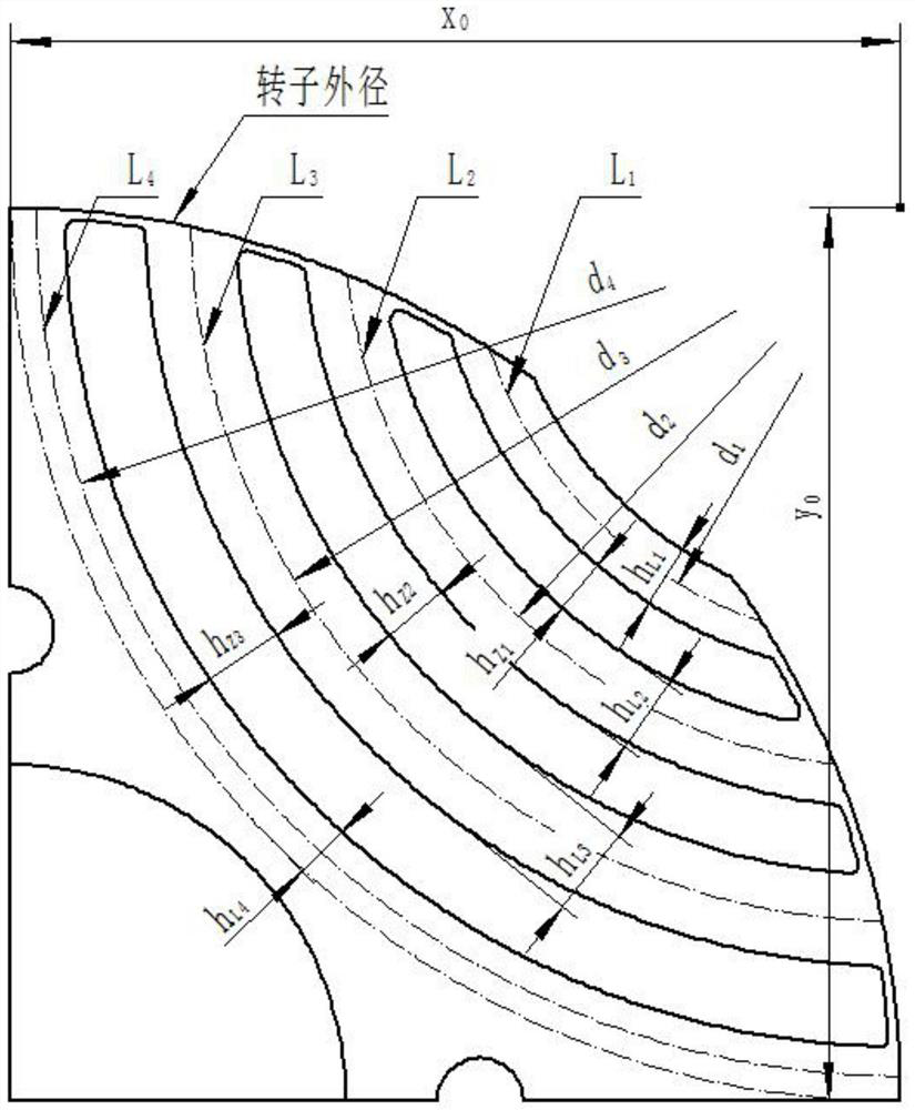
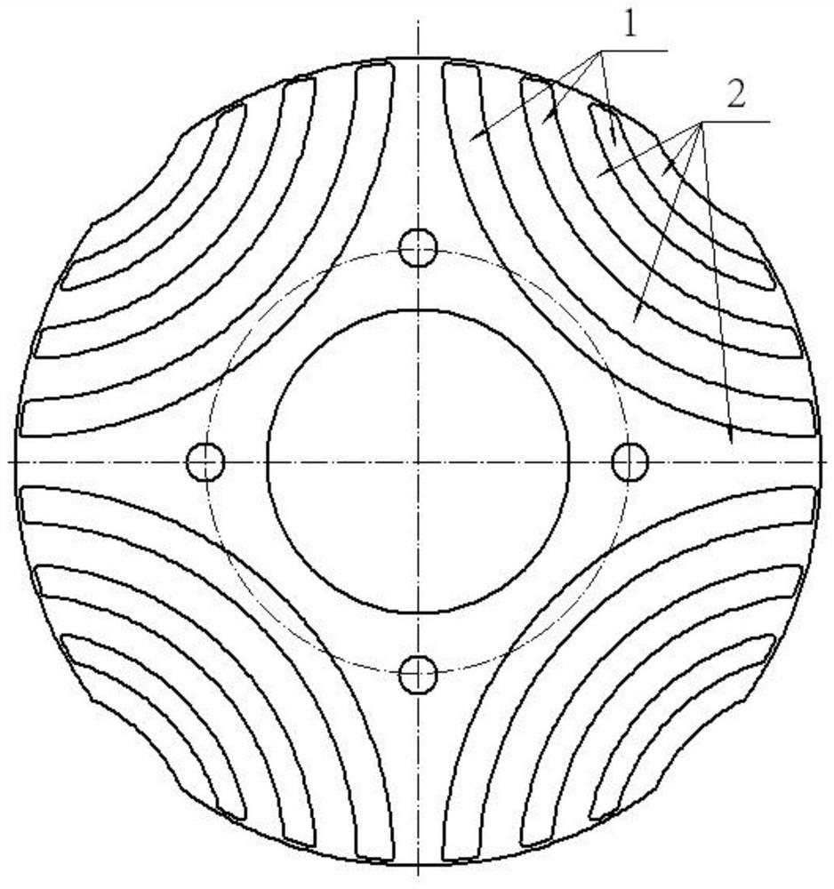
[0044] Take a 4-pole motor as an example, other motors with poles can be implemented as a reference. Rotor core such as figure 1 As shown, the parameters of the rotor core are as follows figure 2 shown.

[0045] Step 1. The number of magnetic barriers in the synchronous reluctance motor rotor is...


PUM


Abstract

The invention relates to a method for designing a rotor core of a low-harmonic synchronous reluctance motor. In the design of the motor, the sine degree of the rotor magnetic conductance is improved through adoption of calculation methods such as the width proportion and the position relation of the rotor magnetic barrier and the magnetic circuit, so that the sine degree of the magnetic flux density is improved, and the harmonic content of the magnetic flux density is reduced. The calculation method has the advantages of convenience in application, high calculation precision and short calculation period. Specifically, the method for designing a rotor core of a low-harmonic synchronous reluctance motor has the following advantages that: the universality is good, the synchronous reluctance motor with any magnetic barrier number can be calculated, by calculating the magnetic conductance of the magnetic circuit of the motor, the sine degree of the magnetic circuit is improved, and the harmonic content of the magnetic circuit of the motor is reduced, regulation can be performed according to a certain harmonic of the magnetic circuit to improve the design pertinence, the calculation is convenient, other calculation software auxiliary operations such as finite elements are not needed, the programming is easy, the circular calculation is convenient, and the design time is saved.

Description

technical field [0001] The invention relates to a rotor core design method for reducing the air-gap magnetic density harmonic content of an inner rotor synchronous reluctance motor, belonging to the technical field of synchronous reluctance motors. Background technique [0002] Synchronous reluctance motor is a high-performance speed-adjustable motor with the advantages of compact structure, high energy density and high efficiency. The structural feature of this kind of motor is that there are multi-layer magnetic barriers on the rotor core, and the motor generates electromagnetic torque from the difference of reluctance between the alternating and direct axes to realize electromechanical energy conversion. Compared with the three-phase asynchronous motor, there is no cast aluminum in the rotor core, so there is no rotor aluminum loss, and the efficiency has obvious advantages; compared with the permanent magnet synchronous motor, there is no rare earth permanent magnet mate...

Claims


Application Information

Patent Timeline
Patent Type & Authority Patents(China)
IPC IPC(8): H02K15/00H02K1/22
CPCH02K1/22H02K15/0006
Inventor 姚丙雷王鸿鹄刘朋鹏
Owner SHANGHAI MOTOR SYST ENERGY SAVING ENG TECH RES CENT
Learn More