
Hydraulic tool changing system and tool changing method of a machining center

A hydraulic and hydraulic pump technology, applied in the field of hydraulic tool change system, can solve the problems of high gas compressibility, large noise, poor work stability, etc., and achieve the effects of high repeat positioning accuracy, rapid tool change and stable work.

Active Publication Date: 2020-03-24
煜雄机器人有限公司
View PDF7 Cites 0 Cited by
  • Summary
  • Abstract
  • Description
  • Claims
  • Application Information

AI Technical Summary

Problems solved by technology

Many CNC machining centers now use air-driven rotary single-arm double-claw manipulators. Due to the high compressibility of gas and low working pressure, this type of manipulator has poor working stability, large structural volume, and difficult tool change process. There is a lot of noise in

Method used


Image

  • Hydraulic tool changing system and tool changing method of a machining center
  • Hydraulic tool changing system and tool changing method of a machining center
  • Hydraulic tool changing system and tool changing method of a machining center

Examples


Embodiment Construction

[0023] The present invention will be further described below in conjunction with specific examples.

[0024] The present invention will be described in detail below in conjunction with specific embodiments shown in the accompanying drawings. However, these embodiments do not limit the present invention, and any structural, method, or functional changes made by those skilled in the art according to these embodiments are included in the protection scope of the present invention.

[0025] The application principle of the present invention will be further described below in conjunction with the accompanying drawings and specific embodiments. Generally speaking, there are two schemes for the tool changer of the manipulator in the machining center: the first scheme is to use hydraulic drive and special structure cylindrical camshaft and knife arm guide sleeve. The second scheme is to use hydraulic drive and various types of cylinders to realize different actions of the manipulator....


PUM


Abstract

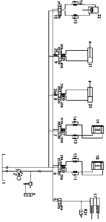
The invention discloses a hydraulic cutter changing system of a machining center; the hydraulic cutter changing problem is solved; and a manipulator automatic cutter changing hydraulic system of the machining center realizes the transfer of power and energy between a tool magazine and a machine tool main shaft and the loading and the unloading of a tool changing device, and achieves the function of finishing automatic changing of a certain number of stored cutters. The automatic tool changing device can be hydraulically driven to save the auxiliary time of a numerical control machine tool, and can meet multi-procedure and multi-step machining requirements in once installation. The hydraulic system drives a manipulator of the machining center to automatically change the cutters to achieve the characteristics of quick cutter changing, short time, high repeated positioning precision, enough cutter storage quantity and stable work.

Description

technical field [0001] The invention relates to the field of machine tools, and more specifically, relates to a hydraulic tool changing system of a machining center. Background technique [0002] The technical level of functional components, the pros and cons of performance, and the overall social supporting level all directly determine and affect the technical level and performance of CNC machine tools. The automatic tool changer of the manipulator is the key functional component for the stable and reliable operation of the machining center. If the design of the automatic tool changer of the manipulator is unreasonable or fails, it will affect the efficiency and reliability of the machining performance of the machining center. According to data, the failure rate of the tool magazine and manipulator accounts for about 25% of the failure rate of the whole machine. Therefore, the reliability of the automatic tool changer directly affects the performance, quality and variety ...

Claims


Application Information

Patent Timeline
Patent Type & Authority Patents(China)
IPC IPC(8): B23Q3/155
CPCB23Q3/155B23Q3/1554
Inventor 荀为君
Owner 煜雄机器人有限公司
Learn More