Metal machining debris collecting device

A collection device and metal processing technology, used in metal processing equipment, grinding/polishing safety devices, manufacturing tools, etc., can solve the problems of metal chips or metal chips with many gaps, accelerated metal corrosion, and occupy more space. , to reduce the space occupied, avoid damage, and prevent damage

Inactive Publication Date: 2019-09-20
徐州三美电器科技有限公司
View PDF4 Cites 4 Cited by
  • Summary
  • Abstract
  • Description
  • Claims
  • Application Information

AI Technical Summary

Problems solved by technology

[0003] In the process of metal processing, a large amount of metal chips or metal scraps are produced; the generated metal chips or metal scraps need to be collected for recycling; but people often simply collect the scraps in the collection box; In addition, metal processing needs to use grinding fluid, and the metal scraps or metal scraps collected in the collection box are often mixed with grinding fluid. The existence of grinding fluid will accelerate the corrosion of metal; metal scraps or metal scraps There are many gaps between the strips, which need to take up more space to store them. In addition, when the metal scraps or metal scraps stored in the collection box are processed, due to the sharp edges and corners of the metal scraps or metal scraps Easy to cause injury to staff

Method used


Image

  • Metal machining debris collecting device
  • Metal machining debris collecting device
  • Metal machining debris collecting device

Examples


Embodiment Construction

[0038] The following will clearly and completely describe the technical solutions in the embodiments of the present invention with reference to the accompanying drawings in the embodiments of the present invention. Obviously, the described embodiments are only some, not all, embodiments of the present invention.

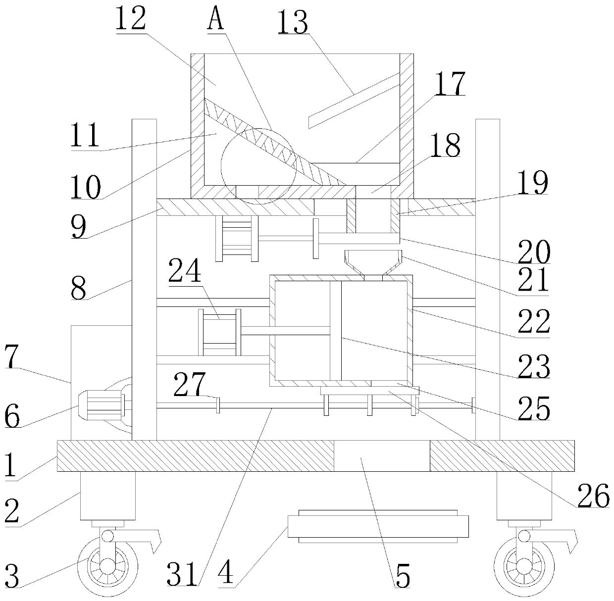
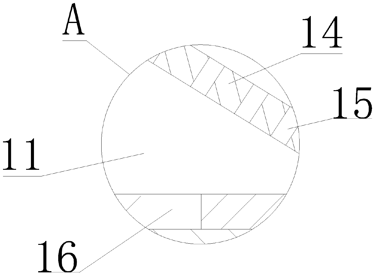
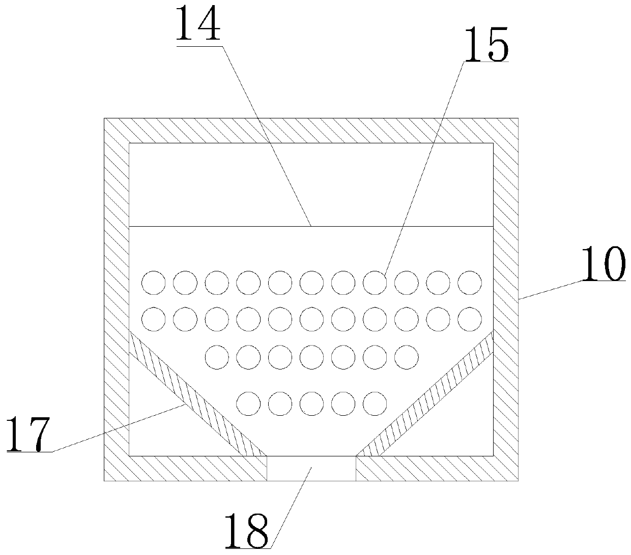
[0039] refer to Figure 1-7 , a metal processing debris collection device, including a base plate 1, a liquid collection box 7, a mounting frame 8, a first mounting plate 9, a material receiving box 10, a sealing assembly, an extrusion box 22, an extrusion plate 23, a first telescopic Device 24 and anti-drop assembly;

[0040] The bottom plate 1 is provided with a liquid collection tank 7 and a mounting frame 8; the mounting frame 8 is provided with a first mounting plate 9; the first mounting plate 9 is provided with a first through hole, and the first mounting plate 9 is provided for receiving metal scraps A material receiving box 10 for shavings; the material rec...


PUM


Abstract

The invention belongs to the technical field of metal debris collection, and particularly relates to a metal machining debris collecting device. According to the scheme aiming at solving the problem that existing metal debris is large in occupied space, the metal machining debris collecting device comprises a bottom plate, a liquid collecting box, a mounting frame, a first mounting plate, a sealing assembly, an extrusion box and an anti-falling assembly; the bottom plate is provided with the liquid collecting box and the mounting frame; the first mounting plate on the mounting frame is provided with a material receiving box; a liquid collecting bin and a debris bin are arranged in the material receiving box; the liquid collecting bin communicates with the liquid collecting box; a discharge pipe is arranged in a discharge hole of the debris bin; the sealing assembly is arranged at a pipe opening at the lower end of the discharge pipe; the discharge pipe communicates with the extrusion bin in the extrusion box; an extrusion plate is arranged in the extrusion box in a sliding mode and is connected with a first telescopic device; and the anti-falling assembly is arranged below the extrusion box. The metal machining debris collecting device can effectively separate debris and grinding liquid after metal machining and squeeze the metal debris to reduce space for metal debris collection, and is easy to operate and convenient to use.

Description

technical field [0001] The invention relates to the technical field of metal scrap collection technology, in particular to a metal processing scrap collection device. Background technique [0002] Metal processing, referred to as metalworking, is a technology that processes metal materials into objects, parts, and components, including large parts such as bridges and ships, as well as tiny components of engines, jewelry, and watches. It is widely used in different fields such as science, industry, art, handicrafts, etc. The progress of human society is closely related to the processing and application of metal materials. [0003] In the process of metal processing, a large amount of metal chips or metal scraps are produced; the generated metal chips or metal scraps need to be collected for recycling; but people often simply collect the scraps in the collection box; In addition, metal processing needs to use grinding fluid, and the metal scraps or metal scraps collected in t...

Claims


Application Information

Patent Timeline
Patent Type & Authority Applications(China)
IPC IPC(8): B24B55/12B24B57/00
CPCB24B55/12B24B57/00
Inventor 曹琳琳
Owner 徐州三美电器科技有限公司
Why Eureka
Try Eureka