A printing control method for a printing system

A control method and printing technology, applied in printing, printing devices, typewriters, etc., can solve the problem of large printing errors, and achieve the effects of accurate coding, effective control, and strong controllability

Active Publication Date: 2021-07-23
DENG QUAN PLASTIC TECH HUNAN CO LTD
View PDF5 Cites 0 Cited by
  • Summary
  • Abstract
  • Description
  • Claims
  • Application Information

AI Technical Summary

Problems solved by technology

[0005] An embodiment of the present invention provides a printing control method for a printing system, aiming to solve the problem of relatively large printing errors in existing coding methods

Method used


Image

  • A printing control method for a printing system
  • A printing control method for a printing system
  • A printing control method for a printing system

Examples


Embodiment 1

[0052] Based on the above description of the jet printing system, this embodiment provides a jet printing control method, and the jet printing control method is applied to the above jet printing system.

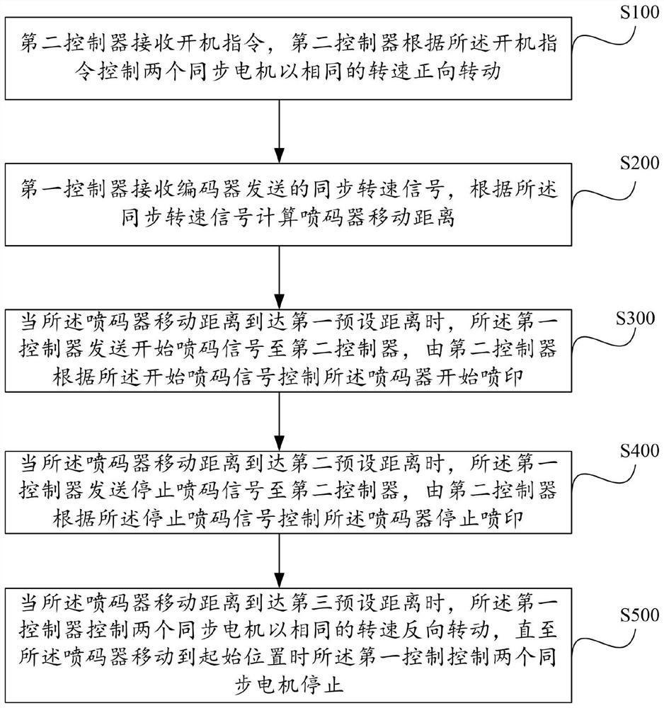
[0053] like figure 1 As shown, a spray printing control method provided by an embodiment of the present invention includes the following steps:

[0054] In step S100, the second controller receives the power-on command, and the second controller controls the two synchronous motors to rotate in the forward direction at the same speed according to the power-on command, the synchronous motor drives the belt to move forward, and the belt drives the inkjet printer Move forward along the rail.

[0055] In a specific implementation process, the power-on command may be a manual switch to turn on the power-on, so as to control the second controller to work, which is used as the power-on command. In this embodiment, the direction in which the code starts to move is designated as the ...

Embodiment 2

[0074] Based on the printing control method of the above-mentioned embodiment, in the specific implementation process, the phenomenon of slippage may occur between the belt and the pulley, and the detection signal of the first controller includes the speed information of the encoder synchronous pulley. The speed information of the synchronous pulley indicates the speed of the belt. The first controller compares the speed information of the synchronous pulley and the speed information of the two synchronous motors to see if they match. If they do not match, it means that there is slippage between the belt and the synchronous pulley. , the first controller sends a signal for adjusting the rotational speed to the second controller, and the second controller controls and adjusts the rotational speed of the two synchronous motors according to the signal.

Embodiment 3

[0076] Based on the above embodiment, when printing is not started, it is necessary to detect whether the pipe material to be sprayed reaches the designated printing area and whether it is facing the printer, and then the first controller sends a power-on command to the second controller to avoid the occurrence of In the case where the spray pipe starts to print before it reaches the print area, this embodiment provides the following two detection methods:

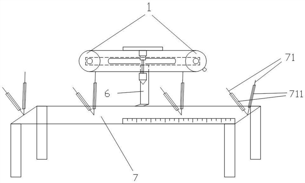
[0077] The printing system also includes a photoelectric switch receiver. Specifically, photoelectric switch receivers are installed at both ends of the guide rail, and photoelectric switch transmitters corresponding to the receivers are installed on the workbench. The two photoelectric switch receivers are electrically connected to the first controller. connect.

[0078] Applied to this jet printing system, a detection method of the jet printing control method provided by this embodiment includes:

[0079] The first cont...


PUM


Abstract

The present invention is applicable to the technical field of pipe material spray printing, and provides a spray printing control method of a spray printing system, comprising: the second controller controls two synchronous motors to rotate forward at the same speed according to the start-up command, and the belt drives the spray printing The encoder moves forward along the guide rail; the first controller calculates the moving distance of the inkjet printer according to the synchronous speed signal; when the moving distance of the inkjet printer reaches the first preset distance, the second controller starts The coding signal controls the inkjet printer to start printing; when the moving distance of the inkjet printer reaches the second preset distance, the second controller controls the inkjet printer to stop printing according to the stop coding signal ; When the moving distance of the inkjet printer reaches the third preset distance, the second controller controls the synchronous motor to rotate in reverse according to the signal, so that accurate inkjet can be realized, and the inkjet is highly controllable.

Description

technical field [0001] The invention belongs to the technical field of character jet printing, and in particular relates to a jet printing control method of a jet printing system. Background technique [0002] The spray code mark of the pipe is used to distinguish the production batch and the manufacturer of the pipe, etc. The code spray refers to the process of printing the mark on the product with the inkjet printer. The mark is set by the coding machine in advance. In a code, each character The spacing is set in advance, and the movement speed of the object to be sprayed or the movement speed of the inkjet printer affects the effect of the inkjet. [0003] The existing spray printing control method of the pipe assembly line generally uses the coder to spray codes continuously according to the movement of the pipe to be sprayed. However, due to the heavy weight of the pipe to be sprayed, the movement speed is prone to large errors, especially when spraying When the charac...

Claims


Application Information

Patent Timeline
Patent Type & Authority Patents(China)
IPC IPC(8): B41J29/393B41J3/44B41J3/407B41J3/01
CPCB41J3/01B41J3/4073B41J3/445B41J29/393
Inventor 王波涛郑程
Owner DENG QUAN PLASTIC TECH HUNAN CO LTD
Why Eureka
Try Eureka