Optical glass, prefabricated part, optical element and optical instrument

A glass preform and optical glass technology, applied in the field of optical glass, can solve the problems of cracking, reducing the service life of optical glass, reducing the glass yield rate, etc., and achieving the effect of low thermal expansion coefficient

Active Publication Date: 2019-09-20
CDGM OPTICAL GLASS
View PDF6 Cites 11 Cited by
  • Summary
  • Abstract
  • Description
  • Claims
  • Application Information

AI Technical Summary

Problems solved by technology

Due to the large thermal expansion coefficient of optical glass, it is easy to cause cracks during processing, which reduces the yield rate of glass; at the same

Method used


Image

  • Optical glass, prefabricated part, optical element and optical instrument
  • Optical glass, prefabricated part, optical element and optical instrument
  • Optical glass, prefabricated part, optical element and optical instrument

Examples


Embodiment

[0093]

[0094] In order to further clearly illustrate and illustrate the technical solution of the present invention, the following non-limiting examples are provided.

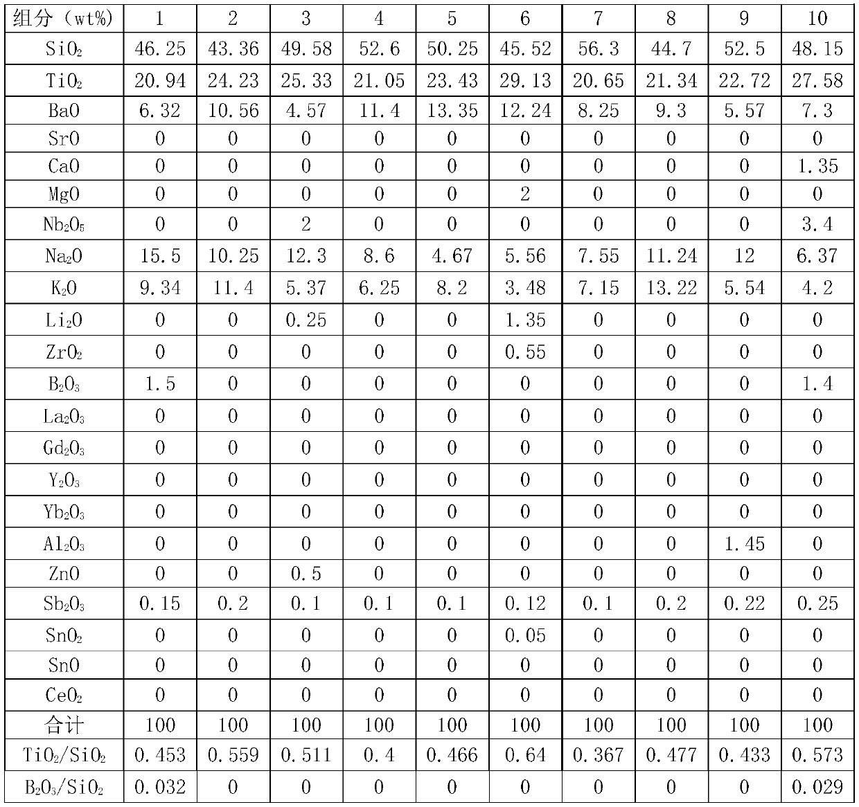
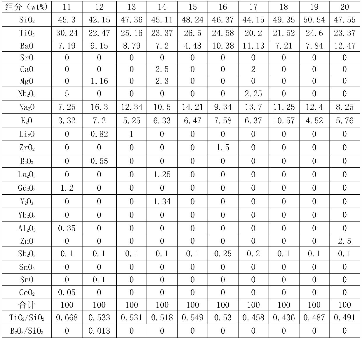
[0095] In this example, the optical glass having the composition shown in Table 1 to Table 2 was obtained by using the above-mentioned manufacturing method of optical glass. In addition, the characteristics of each glass were measured by the test method described in the present invention, and the measurement results are shown in Tables 1 to 2.

[0096] Table 1

[0097]

[0098]

[0099] Table 2

[0100]

[0101]

[0102]

[0103] The glass obtained in Examples 1 to 20 of the optical glass was formed by means of, for example, grinding processing, or compression molding methods such as reheating molding and precision press molding to produce concave meniscus lenses, convex meniscus lenses, and biconvex lenses , Bi-concave lens, plano-convex lens, plano-concave lens and other lens, prism and other preforms.

[0104]

[...


PUM


Abstract

The invention provides optical glass which comprises, in weight percent, 41-58% of SiO2, 18-32% of TiO2, 3-18% of Na2O, 2-15% of K2O and 2-15% of BaO, wherein Na2O/(Na2O+K2O) is 0.3-0.85. By the aid of reasonable component design and ratio, the optical glass meets expected refractive index and abbe number and has low heat expansion coefficient.

Description

Technical field [0001] The invention relates to an optical glass, in particular to an optical glass with a refractive index of 1.63-1.71 and an Abbe number of 28-35. Background technique [0002] In recent years, with the rapid popularization and use of digital cameras, camcorders and camera phones, optical materials have also developed rapidly in the direction of high precision and miniaturization. With the continuous integration of optics, electronic information science, and new material science, optical glass, which is the basic material of optoelectronics, has made rapid progress in the application of optical transmission, optical storage, and photoelectric display. In recent years, optical components and optical instruments have developed rapidly in terms of digitization, integration and high-definition, and higher requirements have been placed on the performance of optical glass used in optical components of optical instruments and equipment. [0003] Optical glass with a re...

Claims


Application Information

Patent Timeline
IPC IPC(8): C03C3/089C03C3/085C03C3/078
CPCC03C3/078C03C3/085C03C3/089
Inventor 孙伟匡波
Owner CDGM OPTICAL GLASS
Why Eureka
Try Eureka