A construction method for underground diaphragm wall joints

An underground diaphragm wall and construction method technology, applied in artificial islands, sheet pile walls, water conservancy projects, etc., can solve the problems of not being able to ensure the sealing of the groove section of the two unit grooves, and not being able to realize side seepage prevention and water retaining. , to achieve the effect of reducing side leakage, flexible use and easy removal

Inactive Publication Date: 2021-06-18
广州穗岩土木科技股份有限公司
View PDF0 Cites 0 Cited by
  • Summary
  • Abstract
  • Description
  • Claims
  • Application Information

AI Technical Summary

Problems solved by technology

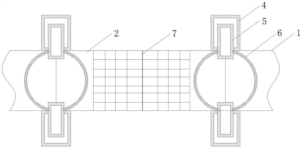
[0003] The shape and installation method of the joint play a decisive role in whether there will be leakage between the pouring groove sections of the underground connecting wall. Leakage occurs between the two unit groove sections, and the side seepage prevention and water retaining effects cannot be achieved. On this basis, a new construction method for the joint of the underground diaphragm wall is proposed. After the joint is constructed and installed , which greatly reduces the leakage between the unit tank sections, and brings convenience to the staff's follow-up operations

Method used


Image

  • A construction method for underground diaphragm wall joints
  • A construction method for underground diaphragm wall joints

Examples


Embodiment Construction

[0024] The following will clearly and completely describe the technical solutions in the embodiments of the present invention with reference to the accompanying drawings in the embodiments of the present invention. Obviously, the described embodiments are only some, not all, embodiments of the present invention. Based on the embodiments of the present invention, all other embodiments obtained by persons of ordinary skill in the art without making creative efforts belong to the protection scope of the present invention.

[0025] In the description of the present invention, it should be noted that, unless otherwise clearly specified and limited, the terms "setting", "installation", "connection" and "connection" should be understood in a broad sense, for example, it can be a fixed connection, or It can be a detachable connection or an integral connection; it can be a mechanical connection or an electrical connection; it can be a direct connection or an indirect connection through ...


PUM


Abstract

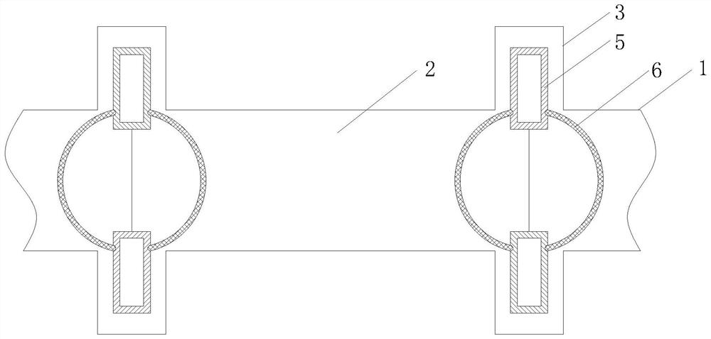
The invention discloses a construction method for underground diaphragm wall joints, which includes construction preparation: designing and marking the size of the guide groove according to the surrounding terrain, dividing the guide groove into several unit grooves; setting the groove holes: The two sides of the connection of all adjacent unit grooves are provided with slot holes of rectangular structure. The small rectangular frame runs through the large rectangular frame to the inside of the guide groove and is at the connection of two unit grooves. The sides of the large rectangular frame and the sides of the small rectangular frame Sliding at joints; clearing holes; hanging joints; hanging steel mesh; pouring underwater concrete; Place guide wall steel bars on the side of the unit tank, build mud tanks and concrete tanks on the side of the unit tank, inject mud into the guide wall steel bars to form a guide wall structure, and the present invention provides a rectangular structure on both sides of the adjacent unit tank connection. Slot holes to realize the pre-installation of the rectangular frame structure. The rectangular frame structure is composed of a large rectangular frame and a small rectangular frame, and the two can slide. The situation of seepage at the gap between the two unit tanks is reduced.

Description

technical field [0001] The invention relates to the related field of underground diaphragm walls, in particular to a construction method for underground diaphragm wall joints. Background technique [0002] Generally speaking, the underground diaphragm wall is a continuous reinforced concrete wall built underground as a water interception, anti-seepage, load-bearing, and water-retaining structure. The underground diaphragm wall is composed of many wall sections. In order to maintain the continuous construction between the wall sections, the joint adopts the lock pipe technology, that is, before pouring the concrete of the groove section, a diameter and groove is pre-inserted at the end of the groove section. Steel pipes with the same width, that is, locking pipes, after the initial setting of the concrete, the steel pipes are slowly pulled out, so that the ends form a semi-tenon-shaped joint. There are also rigid joints set up according to the force requirements of the wall ...

Claims


Application Information

Patent Timeline
Patent Type & Authority Patents(China)
IPC IPC(8): E02D5/18E02D29/16
CPCE02D5/18E02D29/16
Inventor 罗莲花黄辉王欢
Owner 广州穗岩土木科技股份有限公司
Why Eureka
Try Eureka