Novel fabricated column foot connecting node and mounting method thereof

A connection node, prefabricated technology, applied in the direction of architecture, building structure, etc., can solve the problems of less R&D and production, lack of nodes in the position of column bases, etc., to avoid welding, easy installation and disassembly, and easy installation.

Pending Publication Date: 2019-09-20
浙江东南网架股份有限公司
View PDF1 Cites 1 Cited by
  • Summary
  • Abstract
  • Description
  • Claims
  • Application Information

AI Technical Summary

Problems solved by technology

However, because there are few projects to adapt to this special environment, R&D and production are rarely involved, especially the relative lack of nodes at the foot of the column

Method used


Image

  • Novel fabricated column foot connecting node and mounting method thereof
  • Novel fabricated column foot connecting node and mounting method thereof

Examples


Embodiment

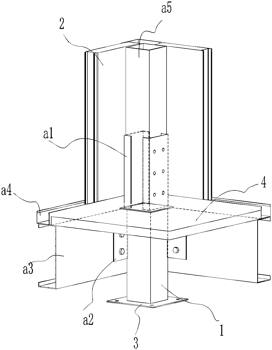
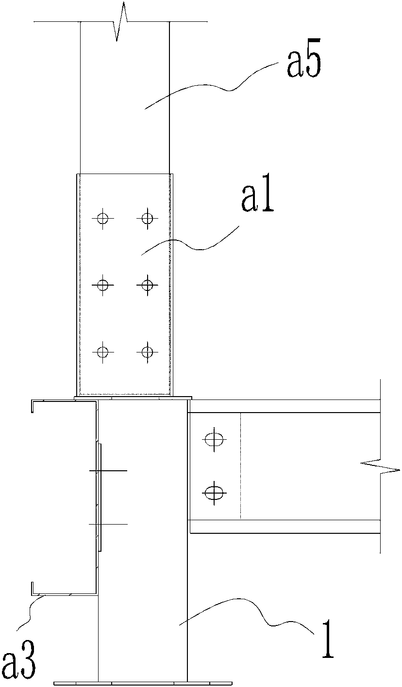
[0026] Embodiment: As shown in the figure, a new type of assembled column foot connection node:

[0027] It includes a bottom steel column and two galvanized C-shaped purlins. The two side walls of the bottom steel column are respectively provided with purlin connecting plates, and the two purlin connecting plates form a 90-degree angle distribution. The upper part of the purlin connecting plate The fixed connection has a pair of symmetrically distributed C-shaped hoops. The outer wall of the purlin connection plate is fixed to the galvanized C-shaped purlin, and the ends of the two galvanized C-shaped purlins form a 90-degree angle distribution. The upper part of the zinc C-shaped purlin is fixed with a U-shaped notch, and the upper steel column is inserted into the two C-shaped hoops, and the upwardly extending wall panel is inserted into the U-shaped notch, and the ends of the two wall panels Form a 90-degree angle distribution.

[0028] The galvanized C-shaped purlin is a...


PUM


Abstract

The invention relates to a connection node, in particular to a novel fabricatedcolumn foot connection node and a mounting method thereof. The novel fabricated column foot connection node comprises a bottom steel column and two C-shaped purlins, a purlin connecting plate is arranged on the two side walls of the bottom steel columnrespectively, the two purlin connecting plates form a 90 degree angle distribution, the upper parts of the purlin connecting platesare fixedly connected with a pair of symmetrically distributed C-shaped hoops, the outer walls of the purlin connecting platesare fixed to galvanized C-shaped purlins, the end parts of the two galvanized C-shaped purlins form the 90 degree angle distribution, the upper parts of the galvanized C-shaped purlins are fixed to U-shaped notches, and upper steel columns are connected into the two C-shaped hoops in an insertion mode, the U-shaped notchesareconnected with upwardly extending wall panels in an insertion mode , the end parts of the two wall panels form the 90 degree angle distribution, andmounting is more convenient.

Description

technical field [0001] The invention relates to a connecting node, specifically a new type of assembled column foot connecting node and its installation method, which can be easily installed by ordinary families independently under special circumstances where the environment is simple and the water and electricity are not connected. , belonging to the field of prefabricated buildings. Background technique [0002] With the development of modern industrial technology, building houses can be manufactured in batches like production. Just transport the prefabricated building components to the site and assemble them. [0003] Since prefabricated buildings are generally used in large buildings, they have higher requirements on the construction site. Cranes, power supplies, and a large number of workers and tools are required, and the requirements for workers' operating skills are relatively high, and the installation is complicated. It cannot be widely used in poor or harsh env...

Claims


Application Information

Patent Timeline
IPC IPC(8): E04B1/24E04B1/58
CPCE04B1/2403E04B2001/2406E04B2001/2421E04B2001/2415E04B2001/2418E04B2001/246Y02E10/50
Inventor 周观根王军赵世伟李乔王玉松项旭吴徐栋
Owner 浙江东南网架股份有限公司
Why Eureka
Try Eureka