Thread mounted pilot pressure reduction second-stage overflow valve

A threaded cartridge, relief valve technology, applied in the field of hydraulic control valves, can solve the problems of not meeting the requirements of short-term heavy-load working conditions of the load spectrum, weight, volume restrictions, and high power density requirements, to enhance the competitiveness of equipment, High adjustment accuracy and good adjustment linearity

Pending Publication Date: 2019-09-20
NINGBO KETAI HYDRAULIC CO LTD
View PDF0 Cites 1 Cited by
  • Summary
  • Abstract
  • Description
  • Claims
  • Application Information

AI Technical Summary

Problems solved by technology

Mobile hydraulic components are an important part of mobile hydraulic technology. The structure of mobile hydraulic components is light, small and compact. There are strict restrictions on their weight and volume, and they require high power density. Usually, they are installed in the form of threaded plug-in, and various components are integrated in the same On the valve body; the load uncertainty of mobile hydraulic machinery is relatively strong, which is mainly reflected in the severe fluctuation of system pressure, so the requirements for the allowable peak pressure, continuous working pressure, life and control accuracy of its components are obviously different from those of industrial hydraulic components. Difference; the power of mobile hydraulic systems often comes from mobile energy sources such as internal combustion engines and batteries, so the power matching between operating loads and energy sources is very emphasized. The current pilot relief valve cannot meet the requirements of short-term heavy-duty working conditions in the load spectrum

Method used


Image

  • Thread mounted pilot pressure reduction second-stage overflow valve
  • Thread mounted pilot pressure reduction second-stage overflow valve

Examples


Embodiment Construction

[0027] The present invention will be further described in detail below in conjunction with the accompanying drawings and embodiments.

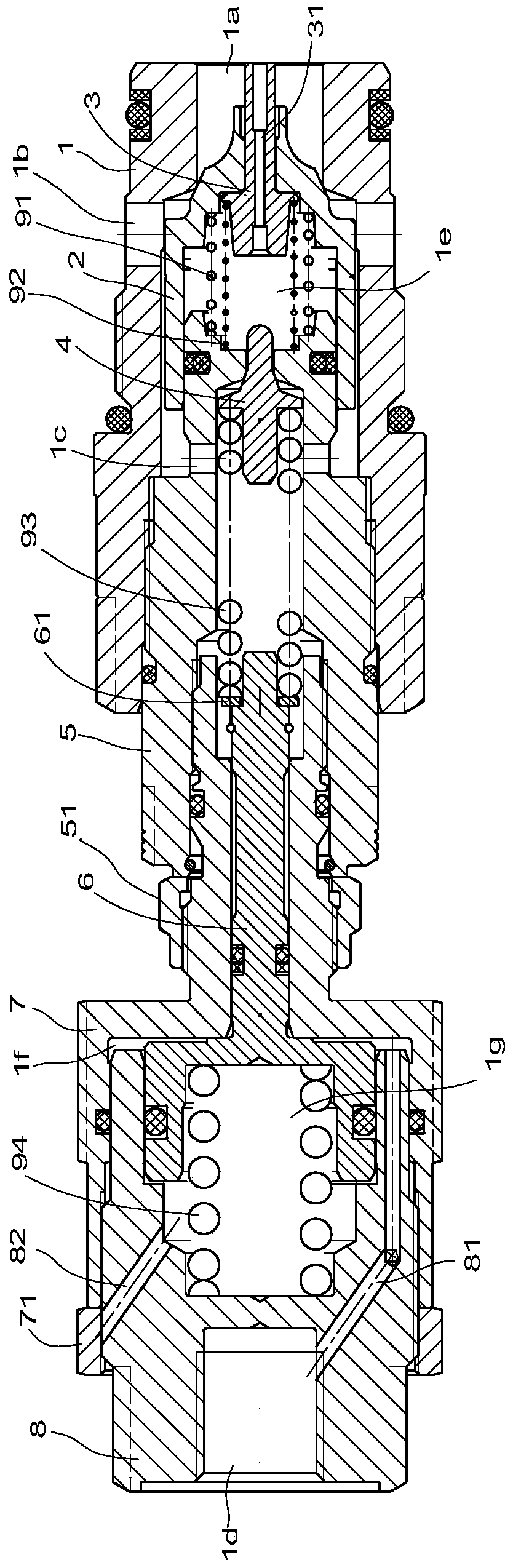
[0028] Such as figure 1 As shown, the threaded cartridge type pilot decompression secondary relief valve in this embodiment includes a main valve sleeve 1, a main valve core 2, a pilot valve seat 5, a slide valve core 3, a first spring 91, and a second spring 92 , Pilot spool 4, pressure regulating valve sleeve 7, piston 6, connecting sleeve 8, third spring 93 and fourth spring 94.

[0029] The main valve sleeve 1 is hollow in the axial direction and forms the first oil port 1a at the front end, and the second oil port 1b is formed on the side wall; the main valve core 2 is movably arranged in the main valve sleeve 1 for controlling the first oil port 1a and On-off of the second oil port 1b.

[0030] The front end of the pilot valve seat 5 is sealingly arranged at the rear end of the main valve core 2, and a first oil chamber 1e is formed be...


PUM


Abstract

The invention provides a thread mounted pilot pressure reduction second-stage overflow valve. The thread mounted pilot pressure reduction second-stage overflow valve is characterized by comprising a main valve sleeve, a main valve element, a pilot valve seat, a sliding valve element, a pilot valve element, a pressure regulation valve sleeve, a piston and a connecting sleeve; the main valve sleeve is hollow in the axial direction, the front end of the main valve sleeve is provided with a first oil port, and the sidewall of the main valve sleeve is provided with a second oil port; the main valve element is movably arranged in the main valve sleeve and used for controlling opening and closing of the first oil port and the second oil port; the front end of the pilot valve seat is arranged at the rear end of the main valve element in a sealed mode, and a first oil chamber is formed between the pilot valve seat and the main valve element; the sliding valve element is arranged on the main valve element, and the middle portion of the sliding valve element is provided with a first oil channel communicating with the first oil chamber and the first oil port. The thread mounted pilot pressure reduction second-stage overflow valve is high in regulation precision and good in regulation linearity, has the one-way oil make-up and pilot pressure reduction functions, realizes accurate limiting control over the loading pressure and ensures safety operation of a hydraulic system.

Description

technical field [0001] The invention relates to an overflow valve, which belongs to the technical field of hydraulic control valves and is mainly used in mobile hydraulic systems. Background technique [0002] Mobile hydraulics are primarily used in vehicles, implements and equipment that move outdoors by themselves. Mobile hydraulic components are an important part of mobile hydraulic technology. The structure of mobile hydraulic components is light, small and compact. There are strict restrictions on their weight and volume, and they require high power density. Usually, they are installed in the form of threaded plug-in, and various components are integrated in the same On the valve body; the load uncertainty of mobile hydraulic machinery is relatively strong, which is mainly reflected in the severe fluctuation of system pressure, so the requirements for the allowable peak pressure, continuous working pressure, life and control accuracy of its components are obviously diff...

Claims


Application Information

Patent Timeline
Patent Type & Authority Applications(China)
IPC IPC(8): F15B13/02
CPCF15B13/024
Inventor 陈磊卞亚琴
Owner NINGBO KETAI HYDRAULIC CO LTD
Why Eureka
Try Eureka