Supercharge Your Innovation With Domain-Expert AI Agents!

Air spring using double conical stack type auxiliary spring

A technology of auxiliary springs and air springs, applied in the direction of springs, spring/shock absorbers, shock absorber-spring combinations, etc., can solve the problems of limited vertical vibration damping effect, complex structure, cumbersome installation, etc., to ensure comfortable operation The effect of increasing the riding comfort and reducing the vertical stiffness

Active Publication Date: 2019-09-20
CRRC QINGDAO SIFANG ROLLING STOCK RES INST +1
View PDF6 Cites 3 Cited by
  • Summary
  • Abstract
  • Description
  • Claims
  • Application Information

AI Technical Summary

Problems solved by technology

However, the emergency spring is limited by the structure and its size is small, so the effect on vertical vibration reduction is limited, and the above structure is complicated and the installation is relatively cumbersome.

Method used


Image

  • Air spring using double conical stack type auxiliary spring
  • Air spring using double conical stack type auxiliary spring
  • Air spring using double conical stack type auxiliary spring

Examples


Embodiment 1

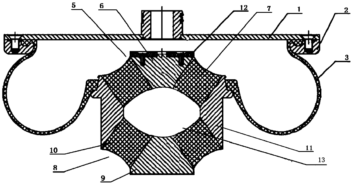
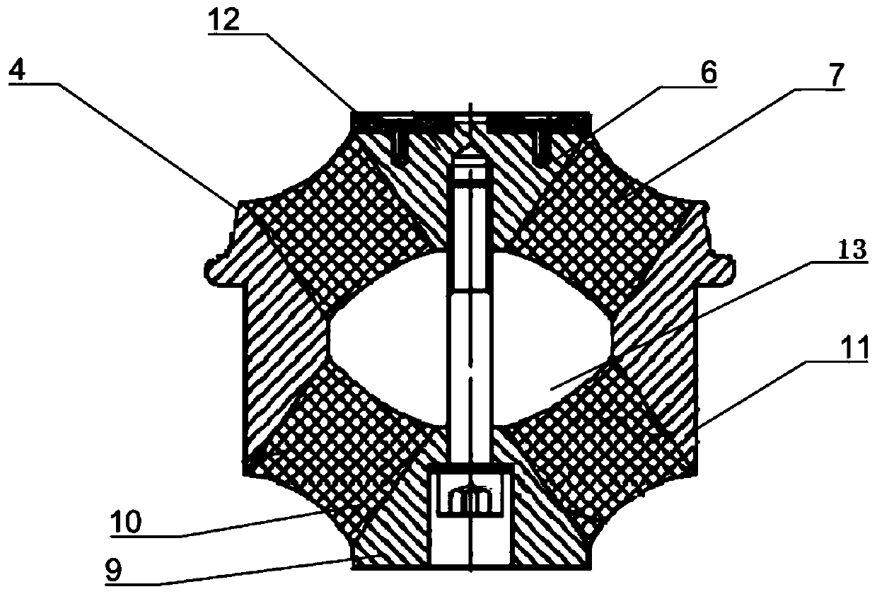
[0024] An air spring that uses a double-cone stack auxiliary spring, such as figure 1 As shown, the air spring system is mainly composed of an upper cover 1, a buckle 2, an air bag 3, an auxiliary spring 4, and a friction block 12. Wherein the auxiliary spring 4 includes an upper cone 5 , a lower cone 8 , and an outer jacket 11 . The upper mouth of the airbag 3 is press-fitted on the loam cake by the buckle 2 through screws, and the lower mouth of the airbag 3 is assembled with the outer coat layer 11 through interference fit. The upper cone 5 is vulcanized by the upper mandrel 6 and the upper rubber stack 7. In this implementation, the upper mandrel 6 is in the shape of a truncated cone, and its upper surface is fixedly connected with the friction block 12 by screws; the rubber stack can be selected There is no separator layer, and multiple separator layers can also be arranged at intervals inside the rubber pile. In this embodiment, it is preferred that there is no separato...

Embodiment 2

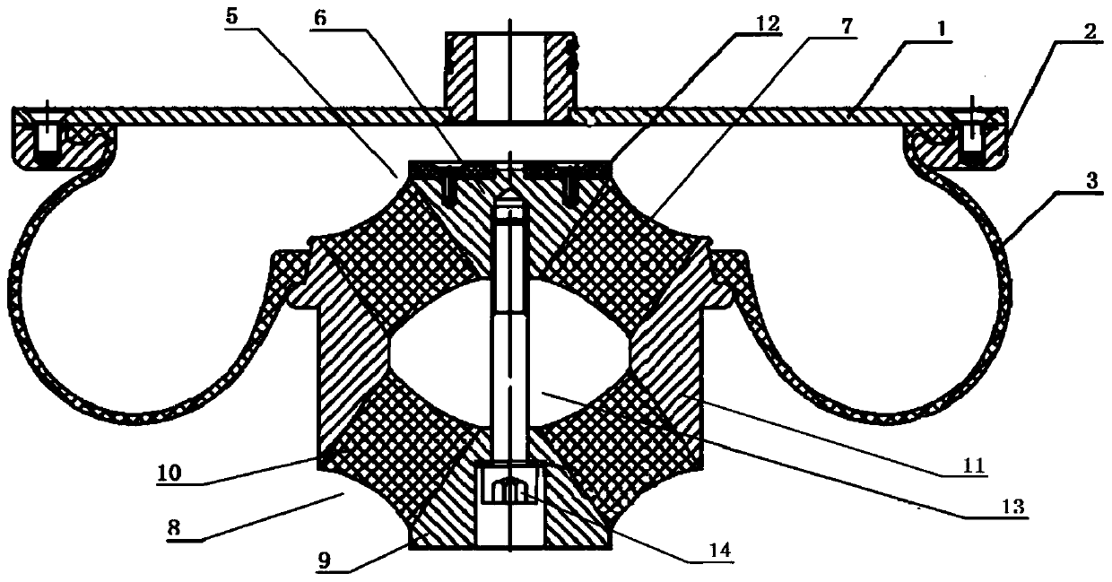
[0029] An air spring that uses a double-cone stack auxiliary spring, such as figure 2 As shown, its structure is different from that of Embodiment 1 in that a pre-tightening bolt 14 is installed at the central axis of the auxiliary spring 4, the pre-tightening bolt connects the upper mandrel 6 and the lower mandrel 9, and the top of the pre-tightening bolt 14 A spacer is placed on the upper surface, and the pre-tightening bolt 14 reduces the height drop of the air spring in an airless state, reduces the variation of the vertical stiffness, and further improves the situation that the vehicle body sinks and damages other components.


PUM


Abstract

The invention provides an air spring using a double conical stack type auxiliary spring. The air spring comprises an upper cover, an airbag and the auxiliary spring. The airbag comprises an upper seam allowance and a lower seam allowance. The upper seam allowance of the airbag is connected to the lower surface of an upper cover in a sealed and fastened manner. The auxiliary spring comprises an upper cone body, a lower cone body and an outer sleeve layer. The upper cone body and the lower cone body are distributed on the inner side of the outer sleeve layer. The outer surface of the upper cone body and the outer surface of the lower cone body are connected with the inner wall of the outer sleeve layer. A flange is arranged on the upper end portion of the outer wall of the outer sleeve layer. The flange is fixedly connected with the lower seam allowance of the airbag. The upper cone body comprises an upper core shaft and an upper rubber stack. The upper rubber stack surrounds the periphery face of the upper core shaft. The lower cone body and the upper cone body are arranged in a mirroring manner. The air spring is simple in structure and convenient to install, the vertical rigidity of the auxiliary spring in the no-gas state can be reduced more effectively, enough displacement can be provided for the vertical direction and the transverse direction, riding comfort is improved, and the dynamic performance of a vehicle in the no-gas state is improved remarkably.

Description

technical field [0001] The invention belongs to the technical field of damping elements of rail vehicle suspension systems, and relates to an air spring using double-cone stack auxiliary springs. Background technique [0002] Air springs are widely used in rail vehicles, as the main component of the secondary suspension system, installed between the car body and the bogie. Air springs are mainly composed of airbags and auxiliary springs. There are three common forms of auxiliary springs: cone type, flat type and hourglass type. At present, when the auxiliary spring is inflated, the air bag and the auxiliary spring work together to provide support for the vehicle body; when the air spring is empty, the air bag will no longer function, and only the auxiliary spring provides support for the vehicle body. As a result, when the auxiliary spring is used in an airless state, the stiffness increases significantly, the deflection is too large, the auxiliary spring is excessively com...

Claims


Application Information

Patent Timeline
IPC IPC(8): F16F13/00B61F5/10
CPCB61F5/10F16F13/002
Inventor 宋红光田清帅刘万强
Owner CRRC QINGDAO SIFANG ROLLING STOCK RES INST
Features
  • R&D
  • Intellectual Property
  • Life Sciences
  • Materials
  • Tech Scout
  • Unparalleled Data Quality
  • Higher Quality Content
  • 60% Fewer Hallucinations
Learn More