
Wheel rim for flywheel rotor and flywheel rotor

A flywheel rotor and rim technology, applied in flywheels, springs/shock absorbers, vibration suppression adjustment, etc., can solve the problem that it is difficult to further increase the energy storage density of the flywheel rotor, the service life of the rim and the flywheel rotor is short, and the flywheel rotor is difficult to surpass. Rotation speed and other issues, to prevent radial delamination and splitting, low density, and increase speed

Inactive Publication Date: 2019-09-20
TSINGHUA UNIV +1
View PDF5 Cites 5 Cited by
  • Summary
  • Abstract
  • Description
  • Claims
  • Application Information

AI Technical Summary

Problems solved by technology

[0003] At present, due to the centrifugal load of the high-speed rotation of the flywheel, the rim of the fiber composite material is deformed in the radial direction, which makes the winding fibers easy to separate and loose, resulting in a short service life of the rim and the flywheel rotor, and making the flywheel rotor It is difficult to exceed the current rotation speed, which makes it difficult to further increase the energy storage density of the flywheel rotor

Method used


Image

  • Wheel rim for flywheel rotor and flywheel rotor

Examples


Embodiment Construction

[0036] Embodiments of the present invention are described in detail below, examples of which are shown in the drawings, wherein the same or similar reference numerals designate the same or similar elements or elements having the same or similar functions throughout. The embodiments described below by referring to the figures are exemplary only for explaining the present invention and should not be construed as limiting the present invention.

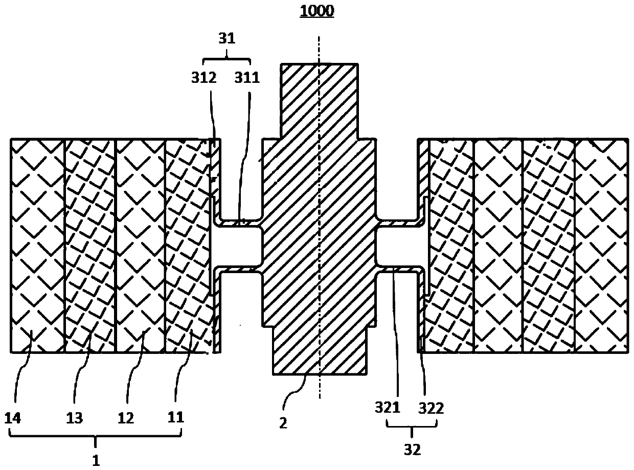
[0037] Refer below figure 1 A rim 1 for a flywheel rotor according to an embodiment of the first aspect of the present invention will be described.

[0038] Such as figure 1 As shown, according to the rim 1 used on the flywheel rotor 1000 according to the embodiment of the first aspect of the present invention, the rim 1 is hollow cylindrical, and the rim 1 is sequentially provided with multi-layer ring shapes on the radial projection plane from the inside to the outside. The fiber composite winding layer, the elastic modulus of the mu...


PUM

PropertyMeasurementUnit
Diameteraaaaaaaaaa
Heightaaaaaaaaaa

Abstract

The invention discloses a wheel rim for a flywheel rotor and the flywheel rotor. The wheel rim is in a hollow cylindrical shape, and a plurality of layers of annular fiber composite material winding layers are sequentially arranged on the radial projection surface of the wheel rim from inside to outside, and elasticity modulus of the plurality of layers of fiber composite material winding layers are gradually increased from the inner layer to the outer layer. The wheel rim is long in service life and capable of further improving the storage energy of the flywheel rotor.

Description

technical field [0001] The invention relates to the technical field of composite material structures, in particular to a wheel rim used on a flywheel rotor and the flywheel rotor. Background technique [0002] There are many small high-speed rotating machines in the industry: such as flywheel energy storage units, centrifuges and turbomolecular pumps, etc., in order to bear the huge centrifugal stress when the rotor rotates at high speed, the structural material of the rotor rim generally adopts high specific strength (high strength, low density) ) super duralumin, titanium alloys and fiber reinforced composites. The stress of the rotating structural parts of the flywheel rotor, such as the rim, increases in a square relationship with the increase of the speed, and is restricted by the strength and density of the metal material, making it difficult for the energy storage density of the rotating flywheel rotor to exceed 40Wh / kg. The density of wound and textile fiber-reinfor...

Claims


Application Information

Patent Timeline
IPC IPC(8): F16F15/30F16F15/305F16F15/315B29C70/30
CPCB29C70/30F16F15/30F16F15/305F16F15/3153Y02E60/16
Inventor 戴兴建徐旸高建军饶聪张剀张小章
Owner TSINGHUA UNIV
Learn More