BIM-based surveying and mapping and lofting equipment

A technology of equipment and surveying instrument, applied in the field of BIM-based surveying, mapping and lofting equipment, can solve problems such as cumbersome operation and error-prone, and achieve the effect of improving comfort, prolonging service life and improving work performance

Active Publication Date: 2019-09-20
陕西国土测绘工程院有限公司
View PDF10 Cites 0 Cited by
  • Summary
  • Abstract
  • Description
  • Claims
  • Application Information

AI Technical Summary

Problems solved by technology

[0003] In addition, in the prior art, manual adjustment bolts need to be used to adjust the position and height of the surveying instrument one by one. However, when adjusting the surveying instrument with multiple support columns that needs to achieve complex multi-degree-of-freedom target position adjustment, it often requires multiple adjustments. Adjustment by bolt is cumbersome and error-prone

Method used


Image

  • BIM-based surveying and mapping and lofting equipment
  • BIM-based surveying and mapping and lofting equipment
  • BIM-based surveying and mapping and lofting equipment

Examples


no. 1 approach

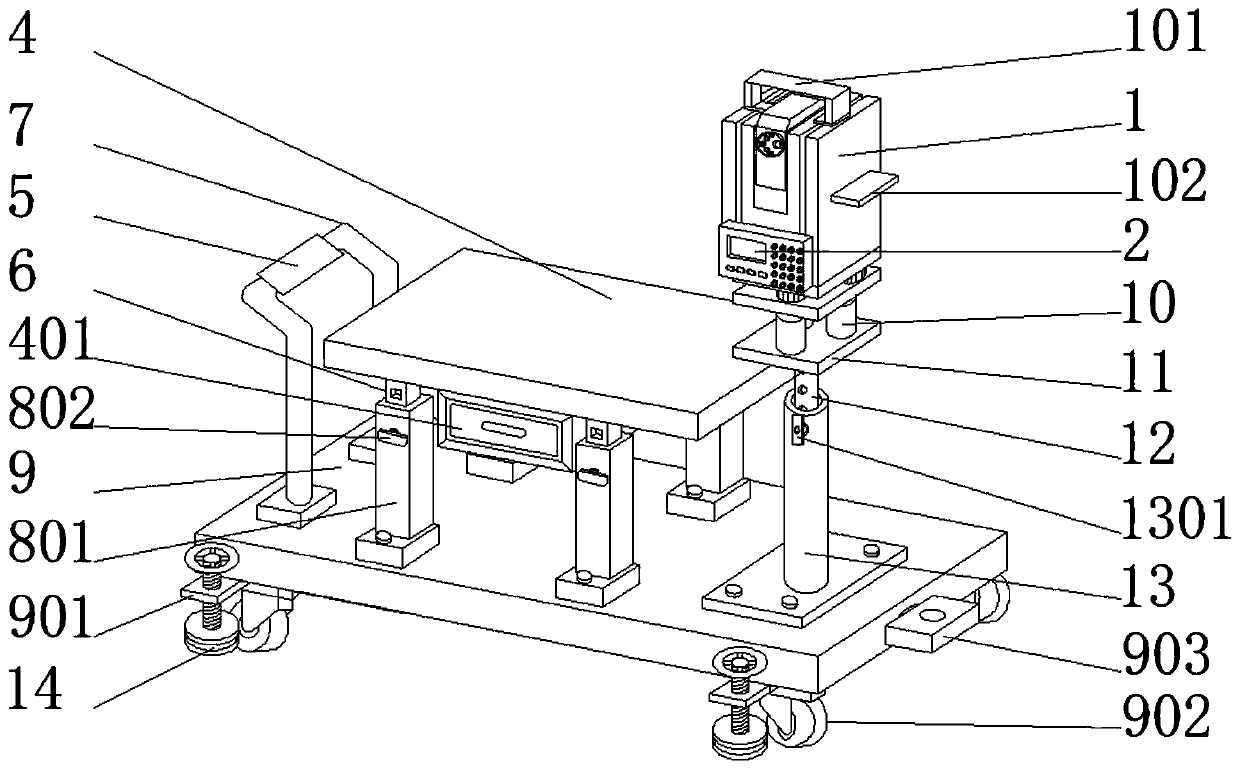
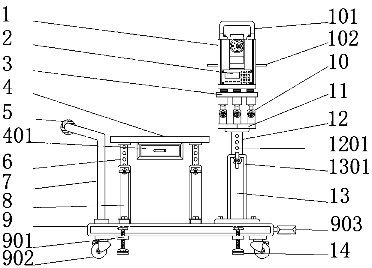
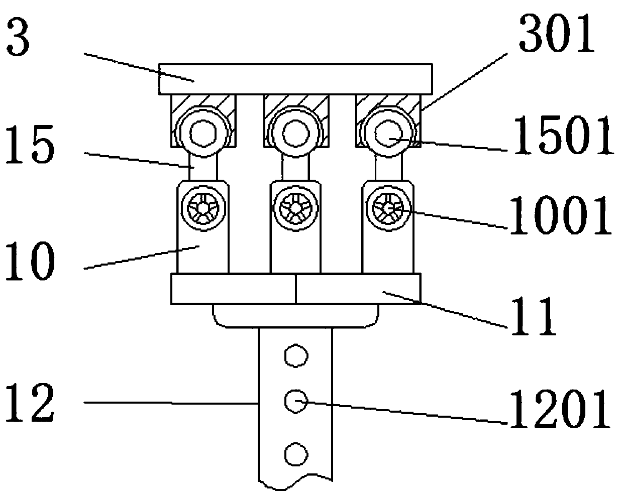
[0026] First implementation: see Figure 1-6, an embodiment provided by the present invention: a BIM-based surveying and setting out equipment, comprising a surveying instrument 1, a desktop 4 and a base 9, by fixing a push handrail 7 on the top of the base 9 on one side of the desktop 4, using the base 9 Moving wheels 902 are fixedly installed at the bottom of the bottom, and the device is moved to a stable place, and a fixed ring 901 is fixedly installed at the bottom of the base 9 between the moving wheels 902, and the inner rotation of the fixed ring 901 is installed with a pad 14 for the position of the device. Fixing, thereby improving the stability of the device, by setting the anti-slip sleeve 5 on the periphery of the push armrest 7, the friction force generated between the surface of the device and the palm of the user can be increased, and the phenomenon of hand slipping during use of the device can be avoided , the surveying instrument 1 is fixedly installed on the...

no. 2 approach

[0037] The second embodiment: a BIM-based surveying and setting-out equipment, including a surveying instrument 1, a desktop 4 and a base 9, the bottom of the base 9 is fixedly equipped with moving wheels 902, and the bottom of the base 9 between the moving wheels 902 is fixed A fixed ring 901 is installed, the inside of the fixed ring 901 is rotatably equipped with a pad 14, the top of the base 9 is fixedly installed with a sleeve 8, the surface of the sleeve 8 is slidingly installed with a limit bolt 802, the sleeve 8 is slidingly installed with a telescopic rod 6, the top of the telescopic rod 6 is fixedly installed with a desktop 4, and a drawer box 401 is fixedly installed between the telescopic rods 6 at the bottom of the desktop 4, and the base on one side of the desktop 4 9 The top is fixedly equipped with a push handrail 7, the periphery of the push handrail 7 is provided with an anti-slip sleeve 5, and the top of the base 9 on the other side of the desktop 4 is fixedl...


PUM


Abstract

The invention discloses BIM-based surveying and mapping and lofting equipment. The equipment comprises a surveying instrument, a desktop and a pedestal. A bottom of the pedestal is fixedly provided with a moving wheel. Telescopic rods are slidably arranged in a casing pipe. Tops of the telescopic rods are fixedly provided with the desktop. A pull box is fixedly arranged among the telescopic rods of the bottom of the desktop. The top of the pedestal of the other side of the desktop is fixedly provided with a circular pipe. An adjusting rod is slidably arranged in the circular pipe. The top of a support bench is fixedly provided with a sleeve connection pipe. A connection rod is slidably arranged in the sleeve connection pipe. The top of a connection bench is fixedly provided with the surveying instrument. Two sides of the surveying instrument are fixedly provided with object placing benches. Through arranging a series of structures, the equipment has advantages that the equipment is convenient to move during a usage process; BIM equipment can be installed; and according to an actual condition, a height of the equipment can be adjusted and so on. And the usage process is optimized.

Description

technical field [0001] The invention relates to the technical field of surveying, mapping and stakeout devices, in particular to a BIM-based surveying, mapping and stakeout equipment. Background technique [0002] BIM (Building Information Modeling) technology was first proposed by Autodesk in 2002, and it has been widely recognized by the industry around the world. It can help realize the integration of building information, from building design, construction, operation to the whole life cycle of the building All kinds of information are always integrated in a 3D model information database. The design team, construction unit, facility operation department and owners can work together based on BIM to effectively improve work efficiency, save resources, reduce costs, and To achieve sustainable development, the core of BIM is to establish a virtual three-dimensional model of architectural engineering and use digital technology to provide this model with a complete architectura...

Claims


Application Information

Patent Timeline
Patent Type & Authority Applications(China)
IPC IPC(8): G01C15/00
CPCG01C15/00
Inventor 芦永豪魏小红张明王巧龙
Owner 陕西国土测绘工程院有限公司
Why Eureka
Try Eureka