Synchronous localization and mapping method for vision-inertia-laser fusion

An inertial and visual technology, used in image enhancement, image analysis, and re-radiation, etc., can solve the problems of easy loss and low SLAM accuracy.

Active Publication Date: 2019-09-20
ZHEJIANG UNIV OF TECH
View PDF3 Cites 66 Cited by
  • Summary
  • Abstract
  • Description
  • Claims
  • Application Information

AI Technical Summary

Problems solved by technology

[0003] In order to overcome the problem that the existing single-sensor SLAM has low precision and is prone to loss in degraded environments, the present invention proposes a method for synchronous positioning and mapping for visual-inertial-las

Method used


Image

  • Synchronous localization and mapping method for vision-inertia-laser fusion
  • Synchronous localization and mapping method for vision-inertia-laser fusion
  • Synchronous localization and mapping method for vision-inertia-laser fusion

Examples


Embodiment Construction

[0061] The present invention will be further described below in conjunction with the accompanying drawings.

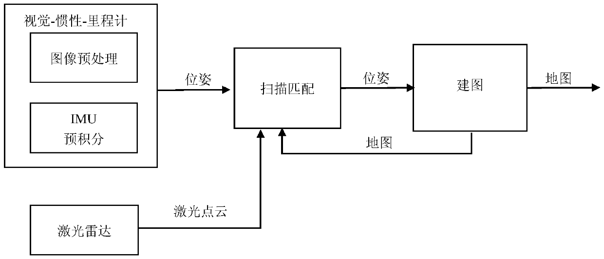
[0062] refer to Figure 1 to Figure 5 , a simultaneous positioning and mapping method for visual-inertial-laser fusion, comprising the following steps:

[0063] 1) Visual-inertial-laser odometer, the process is as follows:

[0064] Assuming that the internal parameters of the camera and the external parameters between the three sensors are known, and the sensors are time-synchronized, the camera and the lidar have the same frequency; this method involves four coordinate systems, namely the world coordinate system W, the camera coordinate System C, inertial measurement unit (IMU) coordinate system I and lidar coordinate system L; sensor coordinate system C, I, L changes with the movement of the device, C i expressed in t i The camera coordinate system at the moment; define the lidar coordinate system after initialization as the world coordinate system;

[0065] Firs...


PUM


Abstract

A synchronous localization and mapping method for vision-inertia-laser fusion mainly relates to the technical fields of multi-sensor fusion, SLAM and the like. In order to solve a problem that single sensor SLAM has low precision and is easy to lose in localization and mapping, the invention provides a robust high precision vision, inertia, laser radar fusion SLAM system. A tightly-coupled visual inertia odometer is further optimized through laser radar scanning and matching so as to obtain a more accurate localization result. And when a camera or a laser radar degenerates, and a visual inertia module or a scanning and matching module can not work normally, a system automatically integrates remaining workable modules to maintain stable pose estimation. In order to remove cumulative errors, loopback detection based on an appearance and neighboring matching based on point cloud are added, and then six-degree-of-freedom pose optimization is performed to maintain global consistency. In the invention, robust high-precision localization and mapping effects can be obtained.

Description

technical field [0001] The invention relates to the technical fields of robot vision, multi-sensor fusion, and simultaneous positioning and mapping (SLAM), and in particular to a method for synchronous positioning and mapping of multi-sensor fusion. Background technique [0002] Simultaneous localization and mapping (SLAM) is a technique for a robot to estimate its own motion in an unknown environment and build a map of the surrounding environment. It has a wide range of applications in areas such as drones, autonomous driving, mobile robot navigation, virtual reality and augmented reality. In order to improve the positioning accuracy and robustness of SLAM in different environments, a lot of research has been done. Since SLAM perceives its own motion and the surrounding environment through sensors installed on the robot, many studies have attempted to improve the performance of motion estimation by integrating multimodal sensors. With the development of technology, the se...

Claims


Application Information

Patent Timeline
IPC IPC(8): G01S17/89G01S17/02G01C11/04G01C21/16G06T7/73
CPCG01S17/89G01C21/165G01C11/04G06T7/73G06T2207/10044G06T2207/10028G01S17/86
Inventor 张剑华潜杰王曾媛甘雨林瑞豪陈胜勇
Owner ZHEJIANG UNIV OF TECH
Why Eureka
Try Eureka