Cable laying and installation cutting and peeling equipment

A cable laying and equipment technology, which is applied in the direction of cable laying equipment, cable installation, cable installation device, etc., can solve the problems of increasing the labor intensity of workers, failing to meet the use requirements, and low work efficiency, so as to ensure the stripping effect and fast Efficient peeling work and the effect of reducing labor intensity

Inactive Publication Date: 2019-09-20
ANHUI TIANMING CABLE
View PDF7 Cites 17 Cited by
  • Summary
  • Abstract
  • Description
  • Claims
  • Application Information

AI Technical Summary

Problems solved by technology

[0002] With the rapid development of China's economy and the continuous improvement of urban modernization, power cables, as traditional Chinese medicine equipment in urban power grids, have developed extremely fast, with an average annual growth rate of 35%. In recent decades, the demand for electric energy During the development, construction, transformation and long-distance transmission of electric energy of large-scale hydropower stations far away from industrial centers, during the laying of cables, the cables are usually cut according to the actual installation size, and then the ends are stripped Installation, the existing devices usually use tool pliers to cut off, but it is laborious to use manual cutting for large-diameter cables, and after cutting, the ends need to be manually peeled, the work efficiency is low, and the The labor intensity of workers cannot meet people's requirements, so it is very meaningful to study a cable laying, installation, cutting and stripping equipment.

Method used


Image

  • Cable laying and installation cutting and peeling equipment
  • Cable laying and installation cutting and peeling equipment
  • Cable laying and installation cutting and peeling equipment

Examples


Embodiment 1

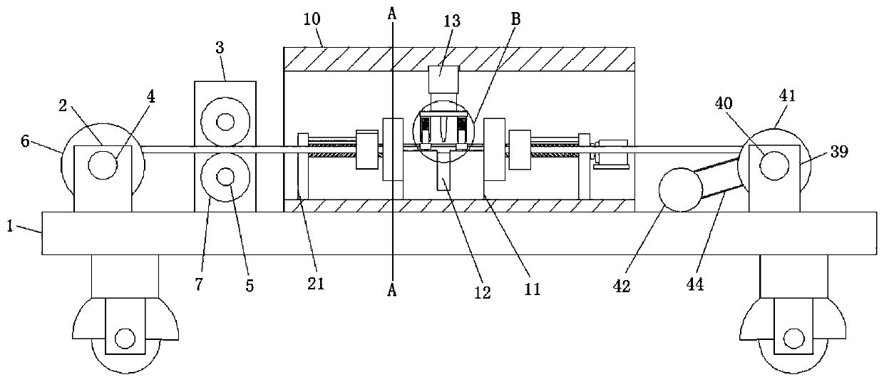
[0029] refer to Figure 1-6, a cable laying installation cutting and peeling equipment, including a workbench 1, the four corners of the lower end surface of the workbench 1 are fixedly connected with support legs by screws, the lower ends of the support legs are equipped with universal wheels, and the upper end surface of the workbench 1 is a The side is fixedly connected with a support seat 2 and a support seat 2 3 by screws, and the support seat 2 3 is located on the side of the support seat 2 close to the center of the workbench 1, and there are two support seats 2 and 2 support seats. The fixed shaft 1 4 and the fixed shaft 2 5 are rotatably connected between the two support seats 1 2 and 2 3 by rolling bearings respectively, and the outer walls of the rods of the fixed shaft 1 4 and the fixed shaft 2 5 are fixedly connected with pay-off rollers by screws respectively. 6 and conveying roller 7, and two fixed shafts 5 are provided with two and symmetrically distributed at ...

Embodiment 2

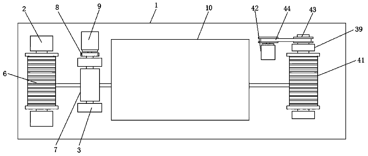
[0032] Such as Figure 1-2 As shown, this embodiment is basically the same as Embodiment 1. Preferably, the other side of the upper end surface of the workbench 1 is fixedly connected with a support base 39 by screws, and two support bases 39 are provided and symmetrically arranged on the workbench 1. At the front and rear end positions, the fixed shaft 3 40 is rotatably connected between the two support seats 39 through rolling bearings, and the outer wall of the rod of the fixed shaft 3 40 is fixedly connected with the winding roller 41 by screws, and the side of the workbench 1 close to the support seat 3 39 The rear end is fixedly connected with servomotor 3 42 by screws, and the output end of servomotor 3 42 and the rear end of fixed shaft 3 40 are all fixedly connected with belt pulley 43 by key, and conveyor belt 44 is connected between the two belt pulleys.

[0033] In this embodiment, the winding roller 41 is provided on the workbench, and the cable is temporarily wou...

Embodiment 3

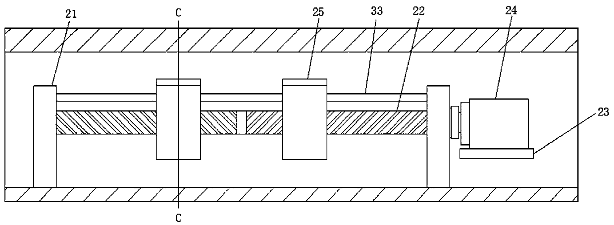
[0035] Such as image 3 and 6 As shown, this embodiment is basically the same as Embodiment 1. Preferably, the upper end of the first briquetting block 19 and the side of the second briquetting block 28 and the third 30 briquetting block are provided with arc grooves matching the cables.

[0036] In this embodiment, the first pressing block 19 , the second pressing block 28 and the third pressing block 30 are provided with arc grooves matching the cables, thereby facilitating the clamping of the cables and making the cutting and pulling of the cables more stable.


PUM


Abstract

The invention discloses cable laying and installation cutting and peeling equipment, which comprises a work bench. The four corners of the lower end surface of the work bench are respectively and fixedly connected with a supporting leg through a screw; the lower end of each supporting leg is equipped with a universal wheel; one side of the upper end surface of the work bench is fixedly connected with support bases 1 and support bases 2 through screws; the support bases 2 are located at the side, close to the center of the work bench, of the support bases 1; the number of the support bases 1 and the number of the support bases 2 are two; a fixation shaft 1 is rotatably connected between the two support bases 1 through a rolling bearing and fixation shafts 2 are rotatably connected between the two support bases 2 through rolling bearings; the rod body outer walls of the fixation shaft 1 and the fixation shafts 2 are fixedly connected with a pay-off roller and a conveying roller through screws respectively; the two fixation shafts 2 are symmetrically arranged at the upper and lower ends of the support base 2; the back sides of the two fixation shafts 2 pass through the support bases 2 and are rotatably connected through a gear set; and the back end of the rear support base 2 is provided with a servo motor 1.

Description

technical field [0001] The invention relates to the technical field of cable laying auxiliary equipment, in particular to a cable laying, installation, cutting and stripping equipment. Background technique [0002] With the rapid development of China's economy and the continuous improvement of urban modernization, power cables, as traditional Chinese medicine equipment in urban power grids, have developed extremely fast, with an average annual growth rate of 35%. In recent decades, the demand for electric energy During the development, construction, transformation and long-distance transmission of electric energy of large-scale hydropower stations far away from industrial centers, during the laying of cables, the cables are usually cut according to the actual installation size, and then the ends are stripped Installation, the existing devices usually use tool pliers to cut off, but it is laborious to use manual cutting for large-diameter cables, and after cutting, the ends n...

Claims


Application Information

Patent Timeline
Patent Type & Authority Applications(China)
IPC IPC(8): H02G1/12H02G1/06
CPCH02G1/06H02G1/126
Inventor 朱星亮
Owner ANHUI TIANMING CABLE
Why Eureka
Try Eureka