hermetic compressor

A closed compressor, compression chamber technology, applied in liquid variable capacity machinery, rotary piston machinery, mechanical equipment, etc., can solve problems such as compression loss and excessive compression, reduce mechanical friction loss, improve compressor Efficiency, effect of preventing refrigerant leakage

Active Publication Date: 2020-10-16
LG ELECTRONICS INC
View PDF9 Cites 0 Cited by
  • Summary
  • Abstract
  • Description
  • Claims
  • Application Information

AI Technical Summary

Problems solved by technology

[0010] At the same time, vane rotary compressors, by their very nature, have shorter compression cycles than typical rotary compressors, which can lead to overcompression, and this overcompression can cause compression losses

Method used


Image

  • hermetic compressor
  • hermetic compressor
  • hermetic compressor

Examples


Embodiment Construction

[0054] Hereinafter, a vane rotary compressor according to the present invention will be described in detail based on embodiments shown in the drawings.

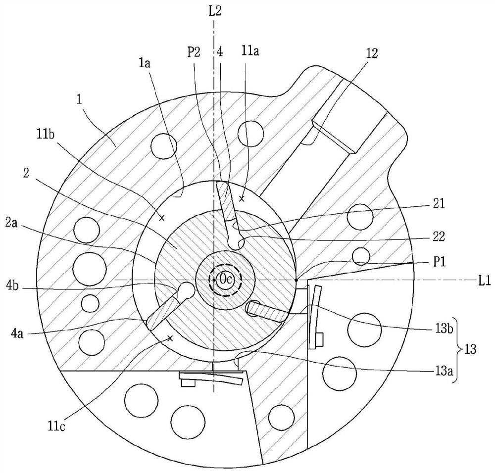
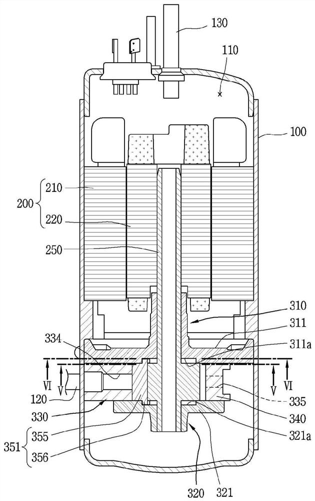
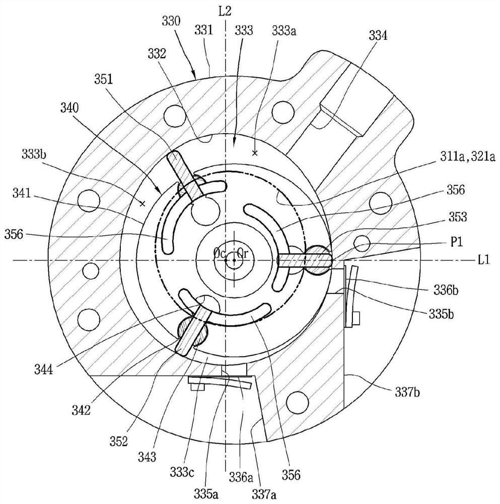
[0055] figure 2 is a longitudinal sectional view of a vane rotary compressor according to the present invention, image 3 is along figure 2 Cross-sectional view of the "V-V" section of the compression section in a rotary vane compressor of .

[0056] like figure 2 As shown, in the vane rotary compressor according to the present invention, the motor section 200 is installed inside the casing 100 , and the compression section 300 mechanically connected through the rotation shaft 250 is installed on one side of the motor section 200 . Depending on how the compressor is installed, the casing 100 may be divided in a vertical or lateral direction, or vertically or laterally. When the housing 100 is divided vertically, the motor section and the compression section are arranged on the upper side and the lower side, respectivel...


PUM


Abstract

A hermetic compressor including blades inserted into rollers, rotated together with the rollers, and pushed toward the inner peripheral portion of the cylinder by the rotation of the rollers to divide a compression chamber into a plurality of spaces, The vane includes: a body portion having a sealing surface in contact with the inner peripheral portion of the cylinder and inserted into the roller; and a guide portion crossing from an axial end of the body portion in a direction in which the vane slides out direction, and it can be slidably inserted into a guide groove formed on at least one of the first bearing and the second bearing to limit the vane toward the inner periphery of the cylinder in at least some part of the circumference of the cylinder part slides off the roller. Thereby, the mechanical friction loss of a blade can be reduced.

Description

technical field [0001] The present invention relates to a hermetic compressor, more specifically to a vane rotary compressor (rotary vane compressor). Background technique [0002] A typical rotary compressor is a type in which rollers and vanes are in contact with each other, and a compression space of a cylinder is divided into a suction chamber and a discharge chamber with respect to the vanes. In such a typical rotary compressor (hereinafter interchangeably referred to as a rotary compressor), the vanes move linearly as the rollers rotate, and thus the suction chamber and the discharge chamber form a variable-volume compression chamber To suck, compress and discharge refrigerant. [0003] In contrast to such rotary compressors, there is also known a vane rotary compressor in which the vanes are inserted into rollers and rotate with the rollers so that they are pushed out by centrifugal force and back pressure A compression chamber is formed. This type of vane rotary c...

Claims


Application Information

Patent Timeline
Patent Type & Authority Patents(China)
IPC IPC(8): F04C18/344F04C28/22F04C29/12F04B39/10
CPCF01C21/0836F01C21/0854F04C23/008F04C18/3442F04C2240/50F04C18/344F04C28/22F04C29/128F04B39/1073F04C18/3447F04C27/001F04C29/12F04C2210/10
Inventor 文石焕姜胜敏李丙哲
Owner LG ELECTRONICS INC
Why Eureka
Try Eureka