Textile machine spinning dust collecting device

A machine-woven dust collection device technology, which is applied in the field of textile manufacturing, can solve the problems of secondary pollution of dust collection, easy blockage of filter devices, and affecting the normal use of dust collectors, so as to prevent secondary pollution and reduce the effect of dust removal

Active Publication Date: 2019-09-24
胡俏俊
View PDF9 Cites 2 Cited by
  • Summary
  • Abstract
  • Description
  • Claims
  • Application Information

AI Technical Summary

Problems solved by technology

[0008] The purpose of the present invention is to provide a textile dust collection device for textile machines to solve the problem that the filter device of the traditional dust remover proposed in the above background technology is easy to block, which affects the normal use of the dust remover during cleaning, increases the workload of personnel, and has secondary dust collection. pollution problem

Method used


Image

  • Textile machine spinning dust collecting device
  • Textile machine spinning dust collecting device
  • Textile machine spinning dust collecting device

Examples


Embodiment 1

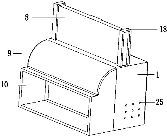
[0028] The present invention provides such as Figure 1-5 A kind of weaving machine weaving dust collecting device shown, comprises main box 1, as figure 1 As shown, the top of the main box 1 is fixedly installed with a solid plate 8 and a limit groove 18, the limit groove 18 limits the solid plate 8, the solid plate 8 can slide up and down in the limit groove 18, and the bottom of the solid plate 8 is installed Dust collection net 7 is arranged, and this dust collection net 7 selects high-strength polyurethane material for use, and intensity is high, and service life is long, and scraper 14 is not easy to be damaged when scraping off dust collection with the lamination movement with it; One side of solid plate 8 is fixedly installed with suction Air box 9, the side wall of suction box 9 is provided with suction port 10, and the air sucked in by suction hole 10 can enter in the air intake box 2 by air inlet 23, and the size of solid plate 8 is the same as the size of air inlet...

Embodiment 2

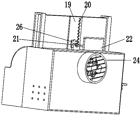
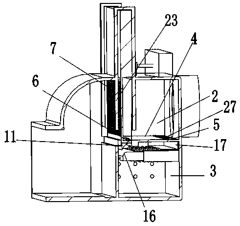
[0032]The controller can be set to control the forward and reverse rotation time and interval length of the stepper motor 22 according to the cleaning time cycle. When the dust removal time is reached, the controller starts the stepper motor 22 to rotate forward, and the stepper motor 22 is driven by the connecting shaft The gear 26 rotates, the gear 26 drives the rack 20 to move, the rack 20 drives the solid plate 8 and the collecting net 7 to move downward, the end plate 6 and the upper arc plate 11 below the collecting net 7 move downward, and when the upper arc plate 11 When in contact with the lower arc-shaped plate 16, the lower arc-shaped plate 16 squeezes the extruded plate 13 connected with it, and the extruded plate 13 moves into the fixed sleeve 12, and at the same time compresses the spring 15, the upper arc-shaped plate 11 and the end plate After 16 passes through the lower arc-shaped plate 16 in turn, the extrusion plate 12 and the spring 15 lose the extrusion for...

Embodiment 3

[0034] When the collection net 7 moved to the lowermost position in the material receiving box 3, the scraper 14 hung up all the textile dust of the collection net 7, and now the solid plate 8 blocked the air inlet 23, because the size of the solid plate 8 and The size of the air inlet 23 is the same, the air in the air intake box 10 is isolated and no longer enters the air intake box 2, and along with the air in the air intake box 2 is continuously discharged by the suction fan 24, the air in the air intake box 2 The air pressure is smaller than the air pressure in the receiving box 3. Under the action of the air pressure in the receiving box 3, the cover plate 27 on the ventilation slot 5 is opened, and the air enters the receiving box 3 from the round hole 25, and passes through the receiving box 17. The dust-collecting bag on the top is then passed into the air intake box 3 through the long ventilation slot 5, and then discharged by the suction fan 24. During this process, ...


PUM


Abstract

A textile machine spinning dust collecting device comprises a main box, a gas inlet box and a material collecting box. A collecting net and a solid plate are arranged in the main box. A lifting plate is arranged on one side of the solid plate. A rack and a gear are arranged in an inner cavity of the lifting plate. A partition plate is arranged between the gas inlet box and the material collecting box. A ventilating long groove is formed in one side of the partition plate. An upper arc-shaped plate is fixed to the bottom of the collecting net. A fixed sleeve and a squeezing plate are fixed to the inner wall of the material collecting box. A spring is arranged between the outer wall of the squeezing plate and the inner wall of the material collecting box. A lower arc-shaped plate is arranged on the top of the squeezing plate. A material collecting groove is formed in the upper side of the fixed sleeve. An air suction fan is fixed to the side wall of the gas inlet box. A scraper is fixed to the inner wall of the material collecting box. A round hole is formed in the side wall of the material collecting box. By means of the textile machine spinning dust collecting device, spinning dust on the collecting net can be automatically cleaned away in time, and blockage is prevented; meanwhile, the spinning dust can be secondarily collected into a dust collecting cloth bag, secondary contamination during processing is prevented, labor intensity is lowered, and the dust removal effect is improved.

Description

technical field [0001] The invention relates to the technical field of textile manufacturing, in particular to a textile machine textile dust collection device. Background technique [0002] Textile machines, also known as spinning machines, looms, cotton spinning machines, etc. Textile machines are tools that process raw materials such as thread, silk, and hemp into silk threads and then weave them into cloth. They are divided into spinning wheels, pedal looms, and modern mechanical looms. , Modern CNC automatic looms, etc. Many of the raw materials of textile machines are short fibers, such as wool, hemp, cotton, etc. These short fiber raw materials are prone to generate a lot of dust during the weaving process. Dust not only pollutes equipment and finished products, but also pollutes the working environment and endangers work. Personnel are in good health. [0003] In order to achieve the purpose of dust removal, dust collectors are often installed in textile places to ...

Claims


Application Information

Patent Timeline
Patent Type & Authority Applications(China)
IPC IPC(8): B01D46/10B01D46/00B01D46/02B08B15/00
CPCB01D46/10B01D46/02B08B15/00B01D46/62B01D46/681
Inventor 朱彩凤
Owner 胡俏俊
Why Eureka
Try Eureka