
Double-headed machine tool

A machine tool and double-head technology, which is applied in manufacturing tools, metal processing, metal processing equipment, etc., can solve the problems of wasted space, increased volume and weight, and the processing efficiency of single-head is not as good as that of double-heads.

Active Publication Date: 2019-09-24
艾格玛科技股份有限公司
View PDF9 Cites 0 Cited by
  • Summary
  • Abstract
  • Description
  • Claims
  • Application Information

AI Technical Summary

Problems solved by technology

[0002] It is known that China Taiwan I586463 patent has two machine heads sharing two line rails respectively, and its span must be wider, so its volume and weight will inevitably increase, and then there will be larger dimensional deformation, thus affecting the processing accuracy; known European EP1479475 patent, it is arranged on three line rails with a machine head and has only one driving screw, but does not have the configuration of double machine head, and it is too wasteful of space, and the processing efficiency of single machine head is also not as good as double machine head; Therefore , the known technology still needs to be improved

Method used


Image

  • Double-headed machine tool
  • Double-headed machine tool
  • Double-headed machine tool

Examples


Embodiment Construction

[0035] Below in conjunction with accompanying drawing and embodiment the present invention will be further described:

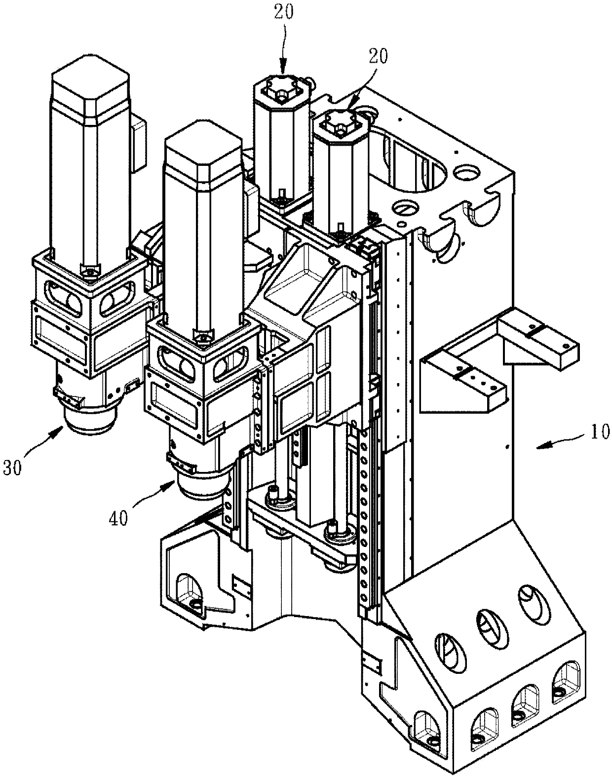
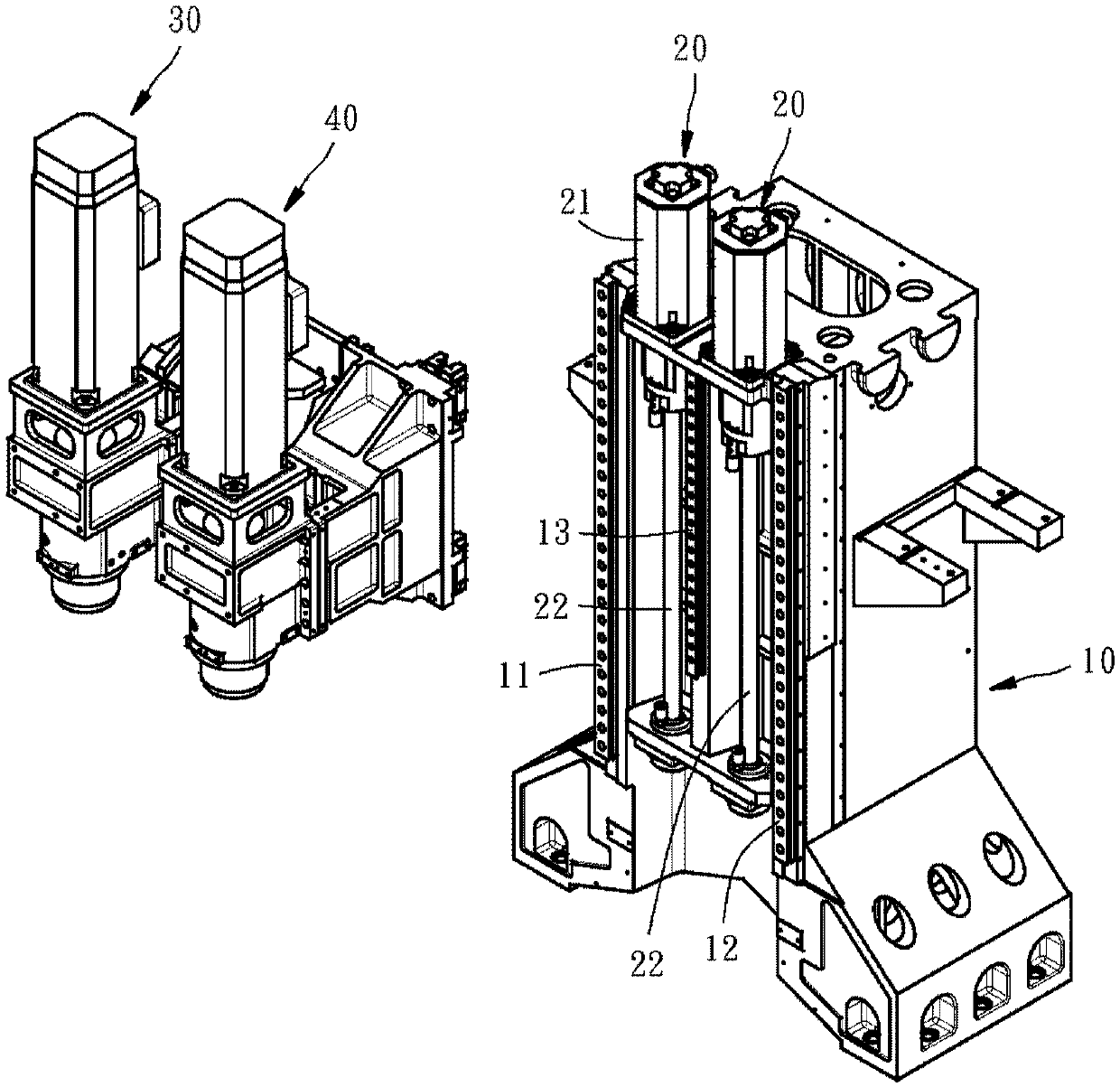
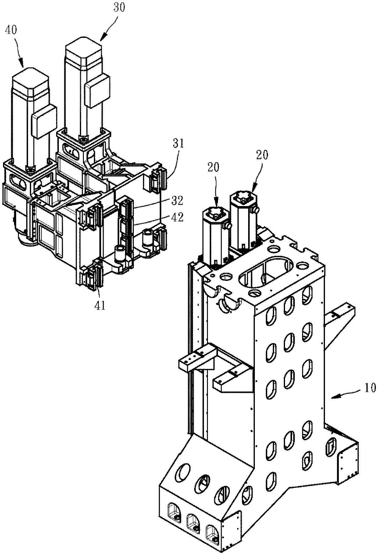
[0036] As shown in each figure, a double-head machine tool provided by the present invention includes:

[0037] A column frame group 10 has a first line rail 11, a second line rail 12, and a third line rail 13 are located between the first line rail 11 and the second line rail 12; in addition, the column frame group 10 There is a line rail fixing part 14 for installing the third line rail 13 .

[0038] Two feed driving groups 20 are installed on the column base group 10 , and each feed driving group 20 has a driving motor 21 and a screw 22 driven by the motor 21 to rotate.

[0039] Wherein, the line rail fixing portion 14 of the column frame set 10 is located between the two screw rods 22 .

[0040] A first machine head 30 has two first sliders 31 slidingly fitted on the first line rail 11, two second sliders 32 slidingly fitted on the third line rail 13, a...


PUM


Abstract

A double-headed machine tool comprises a stand column machine base set which is provided with a first linear rail, a second linear rail and a third linear rail arranged between the first linear rail and the second linear rail; two feeding driving sets arranged on the stand column machine base set, each feeding driving set being provided with a driving motor and a screw rod which is driven by the motor to rotate; a first head provided with a first sliding block matched with the first linear rail in a sliding manner, a second sliding block matched with the third linear rail in a sliding manner, a screw barrel matched with the screw of one feeding driving set in a threaded manner, and a main shaft unit; a second head provided with a first sliding block which is matched with the second linear rail in a sliding mode, a second sliding block which is matched with the third linear rail in a sliding mode, a screw barrel which is matched with the screw rod of the other feeding driving set in a threaded mode, and a main shaft unit.

Description

technical field [0001] The invention relates to processing machinery, in particular to a machine tool with improved line rail and machine head configuration. Background technique [0002] It is known that China Taiwan I586463 patent has two machine heads sharing two line rails respectively, and its span must be wider, so its volume and weight will inevitably increase, and then there will be larger dimensional deformation, thus affecting the processing accuracy; known European EP1479475 patent, it is arranged on three line rails with a machine head and has only one driving screw, but does not have the configuration of double machine head, and it is too wasteful of space, and the processing efficiency of single machine head is also not as good as double machine head; Therefore , the known technology still needs to be improved. Contents of the invention [0003] In view of the above-mentioned defects of the prior art, the main purpose of the present invention is to provide a...

Claims


Application Information

Patent Timeline
IPC IPC(8): B23Q1/44B23Q5/00B23Q1/46
CPCB23Q1/44B23Q1/46B23Q5/00
Inventor 庄敏欣
Owner 艾格玛科技股份有限公司
Learn More