An automatic access system for medical maintenance tools

A technology for accessing systems and maintenance tools, applied in the field of tool storage equipment, can solve the problems of simplicity and rudeness, constant storage space, and inability to count tool usage, etc., and achieves the effect of various storage forms and properly standardized storage.

Active Publication Date: 2021-11-19
广州多得医疗设备服务有限公司
View PDF0 Cites 0 Cited by
  • Summary
  • Abstract
  • Description
  • Claims
  • Application Information

AI Technical Summary

Problems solved by technology

Nowadays, tool racks are generally used to place various tools, which are simple and rude, and it is impossible to count the use of tools and whether they are missing
The medical maintenance tool rack in the prior art, the tool rack itself is relatively simple, only provides the storage function, cannot count the use of tools, and cannot clean up the used tools, the storage space remains unchanged, and cannot guarantee the proper and standardized storage of the tools , so the realization of an automatic access system for medical maintenance tools that can solve such problems is imperative

Method used


Image

  • An automatic access system for medical maintenance tools
  • An automatic access system for medical maintenance tools
  • An automatic access system for medical maintenance tools

Examples


Embodiment 1

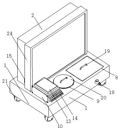
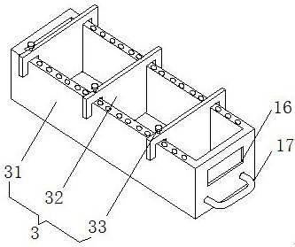
[0025]An automatic access system for medical maintenance tools, including a base plate 1, an access box 2 is provided on the rear side of the upper end of the base plate 1 to realize the storage of tools, and a storage structure is provided in the installation slots evenly distributed on the upper end of the front side of the access box 2 3. The storage structure 3 includes a drawer 31 that is slidably connected in the installation groove to realize tool storage. The two sides of the upper end of the drawer 31 are slidably connected to the chute at the bottom of the partition 32. The upper end of the partition 32 is provided with an adjusting bolt 33 for adjusting The bottom end of bolt 33 is threadedly connected with the evenly distributed threaded holes on both sides of the drawer 31. The front side of drawer 31 in storage structure 3 is provided with numbering plate 16 and handle 17 successively from top to bottom. There are two evenly distributed access slots 4, the bottom ...

Embodiment 2

[0027] The difference between this embodiment and Embodiment 1 is:

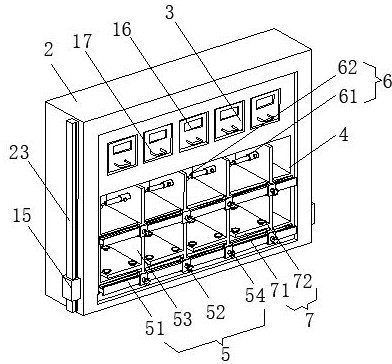
[0028] In this embodiment, the size adjustment structure 5 includes a track 51 arranged at the bottom edge of the front side of the access slot 4, and the upper end of the track 51 is slidably connected with evenly distributed sliders 52, and the upper end of the slider 52 is provided with a partition plate 53 , the rear end of the partition plate 53 extends to the inside of the access slot 4, the front side of the slider 52 is screwed with a locking bolt 54, the inner end of the locking bolt 54 contacts the front surface of the track 51, and the suspension structure 6 Comprising a telescopic column 61 fixedly connected to the left side wall of the partition plate 53 above, the left part of the telescopic end of the telescopic column 61 is provided with a hook 62, and the adsorption structure 7 includes a pendulum fixedly connected to the bottom left side of the partition plate 53 below. Put plate 71, put the...

Embodiment 3

[0031] The difference between this embodiment and Embodiment 1 is:

[0032] In this embodiment, the cleaning device 8 includes a bracket 81 fixedly connected to the inner wall of the mounting groove at the right end of the base plate 1, the bottom end of the bracket 81 is fixedly connected to the center of the upper end of the disc 82, and the chute on the arc surface of the disc 82 is connected to the ring plate The annular slider at the bottom of 83 is slidingly connected, the inner wall of the ring plate 83 is covered with brush strips 86, the bottom of the base plate 1 is provided with a servo motor 84, and the output shaft of the servo motor 84 passes through the bottom through hole of the base plate 1 and extends to In the installation groove, the top of the output shaft of the servo motor 84 is provided with three evenly distributed diagonal braces 85, the top of the diagonal braces 85 is fixedly connected to the bottom surface of the ring plate 83, and the input end of ...


PUM


Abstract

The invention relates to the technical field of tool storage equipment, in particular to an access system for medical maintenance tools. Structure, the front side of the drawer in the storage structure is provided with number plates and handles in sequence from top to bottom. The automatic access system of the medical maintenance tools is equipped with a special storage box for storage tools. The size of the storage position can be adjusted according to the actual situation. , the tools are placed according to the number, and the storage position is stored in a drawer, adsorption or hanging mode, and the storage forms are various. The tools in and out of the warehouse are scanned by the scanner, and the scanned data is timely submitted to the programmable logic controller for integrated management. , Store the data in the memory, and the personnel can check whether the tool is not used or used at any time. The cleaning device and the dust removal and sterilization device can realize the degreasing, cleaning, dust removal and sterilization of the used tools to ensure the proper and standardized storage of the tools.

Description

technical field [0001] The invention relates to the technical field of tool storage equipment, in particular to an automatic access system for medical maintenance tools. Background technique [0002] There are various kinds of medical equipment, and the tools used for their maintenance are also various. In the maintenance of equipment, the management of tools is also very important. Nowadays, tool racks are generally used to place various tools, which are simple and rude, and it is impossible to count the usage and missing of tools. The medical maintenance tool rack in the prior art, the tool rack itself is relatively simple, only provides the storage function, cannot count the use of tools, and cannot clean up the used tools, the storage space remains unchanged, and cannot guarantee the proper and standardized storage of the tools , so the realization of an automatic access system for medical maintenance tools that can solve such problems is imperative. Contents of the i...

Claims


Application Information

Patent Timeline
Patent Type & Authority Patents(China)
IPC IPC(8): B25H3/02B25H5/00B08B1/04B08B3/02B08B5/04A61L2/10
CPCA61L2/10B08B1/002B08B1/04B08B3/02B08B5/04B25H3/028B25H5/00
Inventor 孟建昇
Owner 广州多得医疗设备服务有限公司
Why Eureka
Try Eureka