Filter device for ventilation device of fuel tank of vehicle

A filter device and ventilation device technology, applied in the field of buffer walls, can solve the problems of adverse effects of combustion process, inability to fully recover, and inability to regenerate buffer walls, and achieve the effects of simple cost, simplified production, and uniform flow resistance.

Active Publication Date: 2019-09-24
DR ING H C F PORSCHE AG
View PDF6 Cites 0 Cited by
  • Summary
  • Abstract
  • Description
  • Claims
  • Application Information

AI Technical Summary

Problems solved by technology

However, the application of a negative pressure entails the risk that, in addition to or instead of the tank connection, saturated fuel vapors are re-breathed directly into the engine connection via a shorter path without bypassing the filter device
During the operation of this engine, this leads to the fact that regeneration can only be performed for a very short period, because otherwise the regeneration gases flowing into the internal combustion engine via the engine connection could have a negative composition that could adversely affect the combustion process
However, the use of a so-called buffer wall in the area of ​​the filter housing has the disadvantage that although this bypass prevents a direct overflow from the tank connection into the engine connection, the same section within the filter device cannot Regeneration via the buffer wall
The filter must therefore be designed correspondingly larger, since it cannot be completely restored to the regenerated state

Method used


Image

  • Filter device for ventilation device of fuel tank of vehicle
  • Filter device for ventilation device of fuel tank of vehicle
  • Filter device for ventilation device of fuel tank of vehicle

Examples


Embodiment Construction

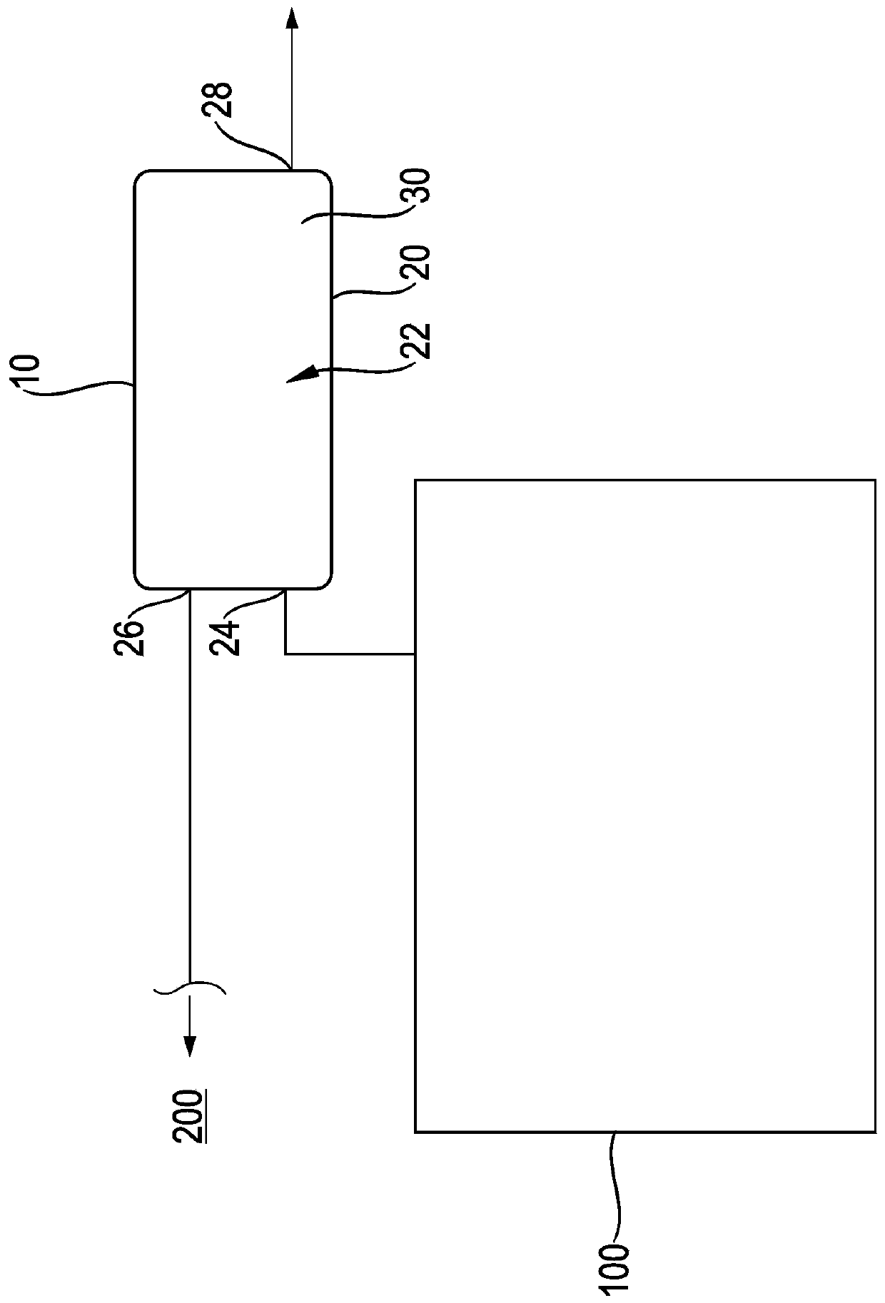
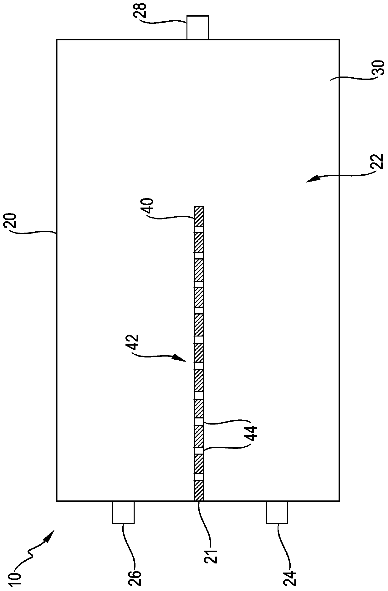
[0028] exist figure 1 In the diagram, the arrangement of the ventilation device for the fuel tank 100 can be seen schematically. Fuel for the internal combustion engine 200 is located in the fuel tank 100 , wherein the supply of the internal combustion engine 200 is provided via a not-shown connecting fluid line between the contents of the fuel tank and the internal combustion engine 200 . If the volume in the fuel tank 100 expands or if a pressure change in the fuel tank 100 occurs due to filling, the excess pressure can be relieved via the ventilation device, in particular via the filter device 10 . In this case, the excess pressure spreads via the tank connection 24 into the filter chamber 22 of the filter housing 20 . There, the excess pressure flows through the sorbent material 30 and the contained fuel vapor is at least partially retained in the sorbent material 30 by adsorption. The gas purified by adsorption in this way can be discharged into the environment of the v...


PUM


Abstract

The invention relates to a filter device (10) for a ventilation device of a fuel tank (100) of a vehicle. The filter device has a filter housing (20) with a filter chamber (22); the filtering chamber is filled with an adsorbing material (30); the adsorbing material is used for at least partially adsorbing fuel vapor; the filter housing has a tank interface (24) for fluid communication with the fuel tank, an engine interface (26) for fluid communication with an internal combustion engine (200) of the vehicle, and a ventilation interface (28) for fluid communication with the environment; a buffer wall (40) is further arranged in the filter chamber between the tank interface and the engine interface (26) for preventing fuel vapor from overflowing to the engine interface (26) from the tank interface (24). The buffer wall (40) has at least one bore section (42) with a through-bore (44) with a flow-rate-dependent flow resistance against the flow of fuel vapor therethrough.

Description

technical field [0001] The invention relates to a filter device for a ventilation system of a fuel tank of a vehicle and to a buffer wall for such a filter device. Background technique [0002] It is well known that the fuel tank of a vehicle must have ventilation. This is generally used to avoid negative pressure in the fuel tank when fuel is being removed from the internal combustion engine. Likewise, when the tank is filled with new fuel through the filling nozzle or when an overpressure in the tank occurs due to thermal expansion at high external temperatures, the overpressure in the tank must be balanced. In the event of overpressure, it must be possible to escape gas from the fuel tank. This is usually released into the environment through the ventilation openings of the ventilation device. In this case, however, it must be ensured that excessive escape of fuel vapors via the ventilation device is avoided. Thus, in known fuel tanks, these ventilation means are equi...

Claims


Application Information

Patent Timeline
Patent Type & Authority Applications(China)
IPC IPC(8): F02M25/08
CPCF02M25/0854B01D53/0407B01D2259/4516
Inventor S·安佐格
Owner DR ING H C F PORSCHE AG
Why Eureka
Try Eureka