Bidirectional engaged transmission device

A transmission and meshing technology, applied in transmissions, transmission parts, gear vibration/noise attenuation, etc., to achieve the effect of simple structure, continuous and stable meshing transmission, and wide application

Inactive Publication Date: 2019-09-24
GUANGXI UNIV
View PDF7 Cites 1 Cited by
  • Summary
  • Abstract
  • Description
  • Claims
  • Application Information

AI Technical Summary

Problems solved by technology

[0007] The invention provides a two-way meshing transmission device to solve the techni

Method used


Image

  • Bidirectional engaged transmission device
  • Bidirectional engaged transmission device
  • Bidirectional engaged transmission device

Examples


Example Embodiment

[0033] The technical solutions in the embodiments of the present invention will be clearly and completely described below with reference to the accompanying drawings in the embodiments of the present invention. It should be understood that the specific embodiments described herein are only used to explain the present invention, but not to limit the present invention. In addition, it should be noted that, for the convenience of description, the drawings only show some but not all structures related to the present invention. Based on the embodiments of the present invention, all other embodiments obtained by those of ordinary skill in the art without creative work fall within the protection scope of the present invention.

[0034] Reference herein to an "embodiment" means that a particular feature, structure, or characteristic described in connection with the embodiment can be included in at least one embodiment of the present invention. The appearance of the phrase in various ...


PUM

PropertyMeasurementUnit
Radianaaaaaaaaaa
Radianaaaaaaaaaa

Abstract

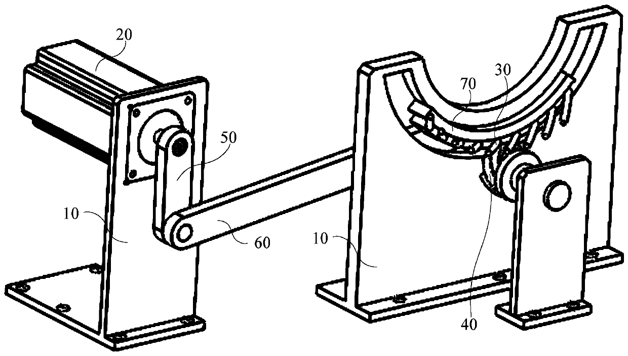
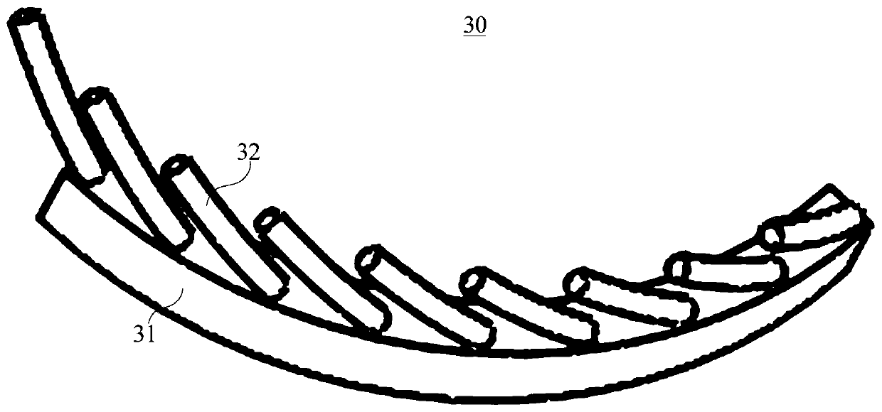
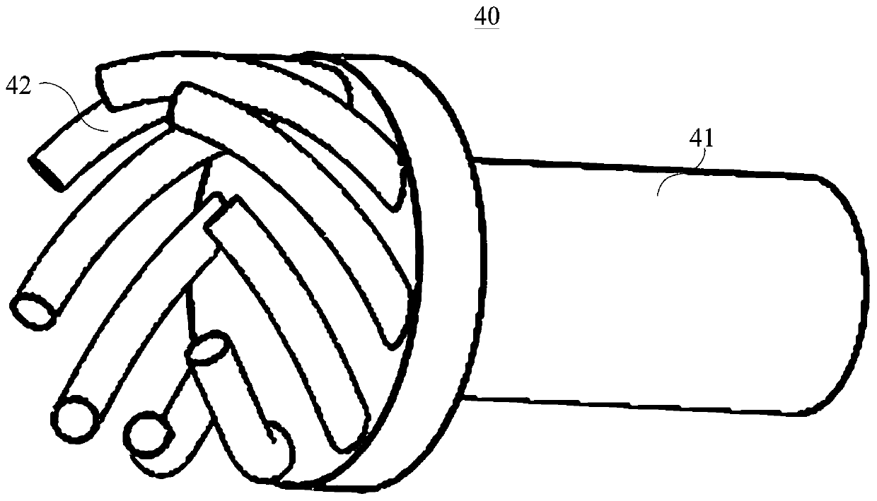
The invention provides a bidirectional engaged transmission device. The bidirectional engaged transmission device comprises a base, a driving member, a crank, a driving gear, a connecting rod and a driven gear; the driving member is connected to the base; the crank is connected to the output end of the driving member; the driving gear includes a driving member and a plurality of driving hook levers, and the multiple driving hook levers are arranged on the end surface of the driving member; two opposite ends of the connecting rod are hinged with the crank and the driving member, respectively; the driven gear includes a driven member and a plurality of driven hook rods, and the multiple driven hook rods are arranged on the end surface of the driven member; and when the driving member drives the crank to rotate, the connecting rod drives the driving member to swing, and therefore continuous engaged transmission is formed between the driving hook levers and the driven hook levers. The engaged transmission of the driving gear and the driven gear of the bidirectional engaged transmission device can achieve continuous and stable bidirectional engaged transmission.

Description

technical field [0001] The present invention relates to the technical field of micro-electromechanical systems, in particular to a bidirectional meshing transmission device. Background technique [0002] With the development of the MEMS field, more and more transmission modes will be applied to the micromechanical components to meet the different motion requirements of the mechanism. Due to the limitation of the volume of the tiny mechanism, the traditional transmission method cannot meet the motion requirements in terms of volume and mass, so various motion transmission methods have been rapidly developed in the application of mechanism structure. [0003] At present, the methods and mechanisms of micro-mechanical transmission researched and developed by various countries mainly include: [0004] (1) Direct micro-miniaturized mechanical transmission technology of traditional mechanical transmission mechanism. For example, micro-pump mechanism, micro-spring mechanism, micr...

Claims


Application Information

Patent Timeline
IPC IPC(8): F16H37/12F16H57/00
CPCF16H37/12F16H57/0006
Inventor 丁江韦玉庭耿婷
Owner GUANGXI UNIV
Why Eureka
Try Eureka