Hydration sintering device
A technology of a sintering device and a sintering furnace, which is applied in the sintering field, can solve the problems of complex sintering process and equipment, and achieve the effects of ensuring the uniformity and consistency of materials and short holding time.
- Summary
- Abstract
- Description
- Claims
- Application Information
AI Technical Summary
Problems solved by technology
Method used
Image

Examples
Embodiment 1
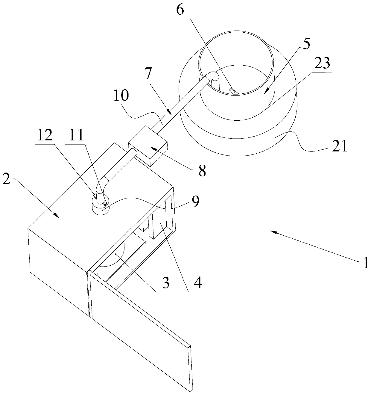
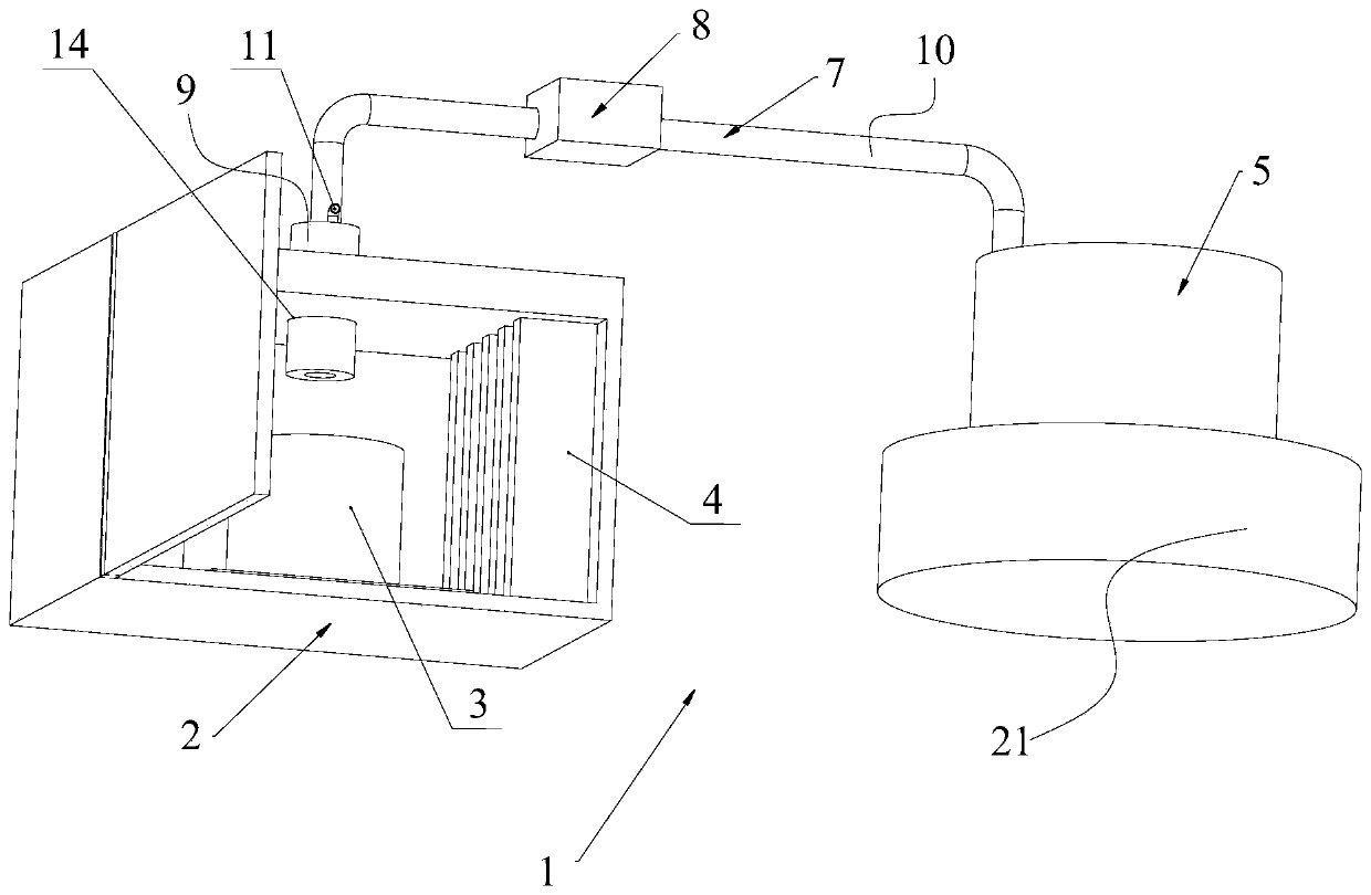
[0065] Such as figure 1 and 2 Shown, a kind of hydration sintering device 1 comprises:
[0066] A sintering furnace 2 with a sintering vessel 3 and a heating element 4 installed inside;
[0067] Material storage container 5, is used for storing water-based slurry;
[0068] The stirring element 6 is arranged in the material storage container 5 and is used for stirring the water-based slurry;
[0069] Stirring drive element (omitted and not shown in the figure), used to drive the stirring element 6 to rotate;
[0070] A delivery pipeline 7 for connecting the sintering furnace 2 and the storage container 5;
[0071] The conveying device 8 cooperates with the conveying pipeline 7 and is used for conveying the water-based slurry in the storage container 5 to the sintering container 3 of the sintering furnace 2 .
[0072] The working principle of the hydration sintering device 1: the heating element 4 works to heat the sintering container 3, and the conveying device 8 transfers...
Embodiment 2
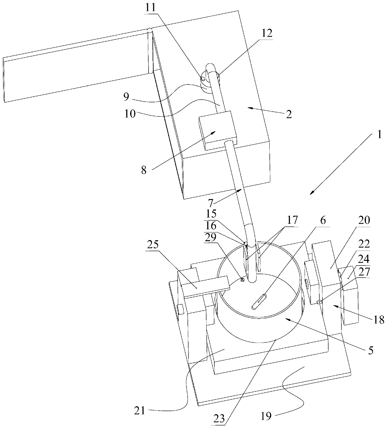
[0086] Such as image 3 , 4 , 5, 6 and 7, the present embodiment discloses another hydration sintering device 1, which mainly has the following differences from embodiment 1:
[0087] 1. If image 3 As shown, in this embodiment, the side wall of the material storage container 5 is equipped with a first magnetic piece 15, and the part where the rubber hose 10 extends into the material storage container 5 is equipped with a second magnetic piece 16, and the first magnetic piece 15 It is magnetically engaged with the second magnetic piece 16 . Through the cooperation of the first magnetic part 15 and the second magnetic part 16, the part of the rubber hose 10 extending into the storage container 5 can be reliably limited, ensuring that the end of the rubber hose 10 is located at the bottom of the storage container 5 and Adjacent to the bottom wall of the storage container 5 . In addition, this matching form also facilitates the separation of the rubber hose 10 from the storag...
Embodiment 3
[0104] Such as Figure 8 As shown, the difference between this embodiment and Embodiment 1 is that in this embodiment, the heat exchange element is a heat exchange coil 13, and the heat exchange coil 13 has a cylindrical structure, and the lower end of the heat exchange coil 13 is located in the positioning groove In 23, the inlet of the heat exchange coil 13 communicates with the liquid outlet 12 of the metal pipe 9, and the outlet of the heat exchange coil 13 communicates with the liquid inlet 11 of the metal pipe 9;
[0105] The material storage container 5 is placed inside the heat exchange coil, the bottom of the material storage container 5 abuts against the bottom wall of the positioning groove 23 , and the stirring drive element is installed on the support base 21 .
[0106] When working, the heat exchange medium in the metal tube 9 is continuously heated, and the heated heat exchange medium is transported to the heat exchange coil by the circulating pump, and the heat...
PUM
| Property | Measurement | Unit |
|---|---|---|
| Bulk density | aaaaa | aaaaa |
| Bulk density | aaaaa | aaaaa |
Abstract
Description
Claims
Application Information
 - R&D
- Intellectual Property
- Life Sciences
- Materials
- Tech Scout
- Unparalleled Data Quality
- Higher Quality Content
- 60% Fewer Hallucinations
Browse by: Latest US Patents, China's latest patents, Technical Efficacy Thesaurus, Application Domain, Technology Topic, Popular Technical Reports.
© 2025 PatSnap. All rights reserved.Legal|Privacy policy|Modern Slavery Act Transparency Statement|Sitemap|About US| Contact US: help@patsnap.com