Laser radar

A lidar and laser technology, applied in the field of radar, can solve the problems of large ranging, limited field of view of the lens, limited radar installation position and function use, etc., to meet the requirements of miniaturization, accuracy and ease of implementation. Effect

Pending Publication Date: 2019-09-24
XIAMEN CITY YAPHA OPTOELECTRONICS TECH
View PDF0 Cites 7 Cited by
  • Summary
  • Abstract
  • Description
  • Claims
  • Application Information

AI Technical Summary

Problems solved by technology

However, due to the requirement of miniaturization of the structure and the limitation of the resolution of the existing imaging sensor, the focal length f of the lens needs to be kept at a relatively large value, that is, the field of view of the lens is li

Method used


Image

  • Laser radar
  • Laser radar
  • Laser radar

Examples


Embodiment 1

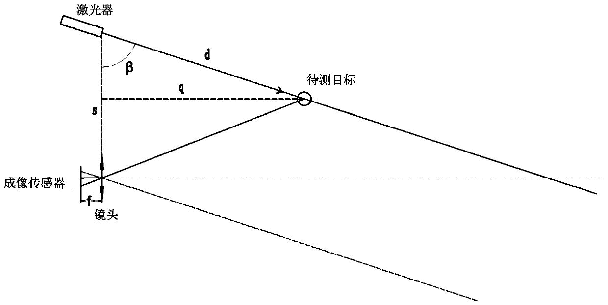
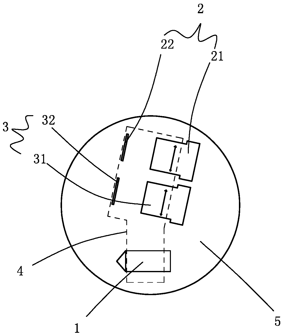
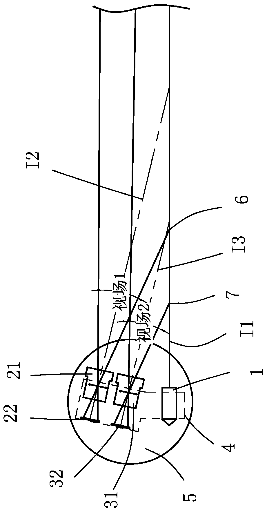
[0032] Such as figure 2 and 3 As shown, a laser radar includes a laser 1 and a receiving system. The laser 1 is used to emit laser light to the target to be measured, and the receiving system is used to receive the laser light reflected back from the target to be measured. For specific principles, please refer to the background technology. Here No more details.

[0033] The receiving system includes a first receiving system 2 and a second receiving system 3, the first receiving system 2 is spaced apart from the laser 1, and the second receiving system 3 is arranged between the first receiving system 2 and the laser 1, The first receiving system 2 is used to receive the laser light reflected back by the target to be measured within the range from the first near point 6 to the first far point (not shown in the figure), the first far point can be taken as infinity, but considering In actual use, it is generally not necessary to detect the infinite distance. In this embodiment,...

Embodiment 2

[0048] The difference between this embodiment and Embodiment 1 is: the receiving system includes a first receiving system, a second receiving system and a third receiving system, the first receiving system is set at intervals from the laser, and the second receiving system is set at Between the first receiving system and the laser, the third receiving system is arranged between the second receiving system and the laser, and the first receiving system is used to receive the target to be measured within the range from the first near point to the first far point The reflected laser light, the second receiving system is used to receive the laser light reflected back from the target to be measured within the range from the second near point to the second far point, and the third receiving system is used to receive the third near point to the third For the laser reflected back by the target to be measured within the range of the far point, the distance from the third near point to th...


PUM


Abstract

The invention relates to the technical field of radar. The invention discloses laser radar. The laser radar comprises a laser and a receiving system, the laser is used for emitting a laser to a target to be detected, the receiving system is used for receiving a laser reflected by the target to be detected, the receiving system at least comprises a first receiving system and a second receiving system, the first receiving system and the laser are arranged at intervals, the second receiving system is arranged between the first receiving system and the laser, the first receiving system is used for receiving the laser reflected by the target to be detected in a range from a first near point to a first far point, the second receiving system is used for receiving a laser reflected by the target to be detected in a range from a second near point to a second far point, and the distance from the second near point to the laser is less than the distance from the first near point to the laser, is smaller than or equal to the distance from the second far point to the laser and is smaller than the distance from the first far point to the laser. The laser radar has an ultra-small blind area or even has no blind area and can meet the miniaturization requirement.

Description

technical field [0001] The invention belongs to the technical field of radar, and in particular relates to a laser radar. Background technique [0002] Lidar has the advantages of relatively simple structure, high monochromaticity, high directionality, good coherence, high measurement accuracy, high spatial resolution, long detection distance, and low price; it has been widely used, and its application range is as large as the atmosphere It is an effective method for high-precision remote sensing detection of sea and land, and it is as small as a household intelligent sweeping robot to navigate and avoid obstacles. [0003] At present, the mechanical single-line scanning lidar mostly uses the triangulation method to obtain distance information. The principle of triangulation distance measurement is: the laser emits a beam of collimated laser light, and the light beam irradiates the target to be measured, and diffuse reflection occurs, and the reflected light is received by ...

Claims


Application Information

Patent Timeline
IPC IPC(8): G01S17/48G01S7/481
CPCG01S7/4816G01S17/48
Inventor 刘敬伟黄运龙余毅祥蔡铭陈君木
Owner XIAMEN CITY YAPHA OPTOELECTRONICS TECH
Why Eureka
Try Eureka