

Efem efem efem and gas replacement method in efem
Patent Information
- Authority / Receiving Office
- CN · China
- Patent Type
- Applications(China)
- Current Assignee / Owner
- SHINKO ELECTRIC CO LTD
- Publication Date
- 2019-09-24
Smart Images
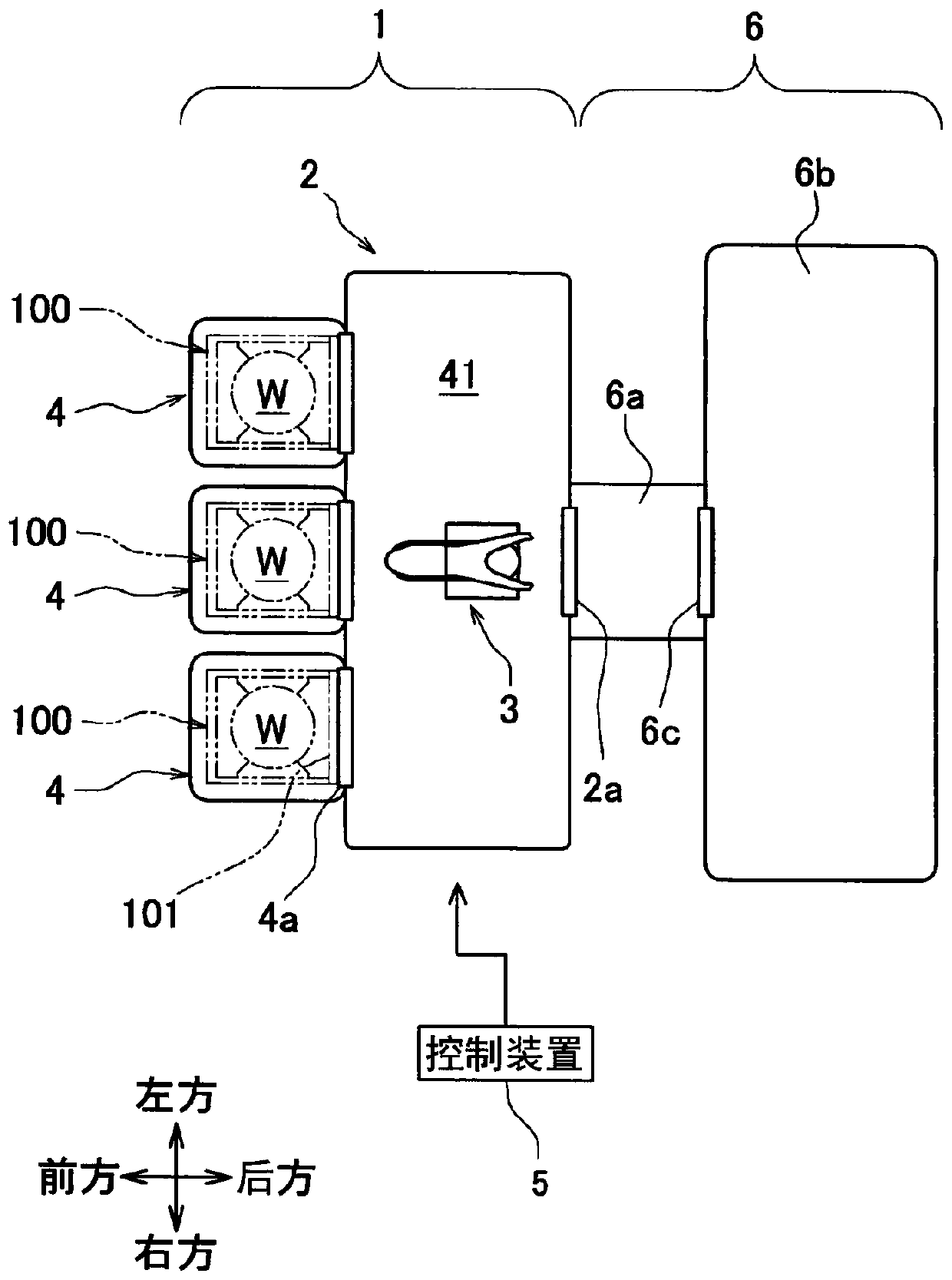
Figure 1 
Figure 2 
Figure 3
Abstract
Description
technical field
[0001] The invention relates to an EFEM (Equipment Front End Module, Equipment Front End Module) capable of circulating inert gas. Background technique
[0002] Patent Document 1 discloses an EFEM that combines a processing device that performs predetermined processing on semiconductor substrates (wafers) and a FOUP (Front-Opening Unified Pod) that accommodates wafers. Handover of wafers between them. The EFEM includes a housing, a loading port, and a transport device. The housing is formed with a transport chamber for transporting wafers. There are multiple loading ports arranged on the outside of the housing, and are used to place FOUPs separately. The transport device is used to transport wafers. The wafers are transported by walking on the extended track in the room.
[0003] In the past, oxygen, moisture, etc. in the transfer chamber had little influence on semiconductor circuits manufactured on wafers, but in recent years, the above influence has beco...