Rail system

A track and rail technology, applied in the field of track systems, can solve the problems of reduced static bearing capacity, low initial frequency of vibration isolation, and increased transmission rate, etc.

Pending Publication Date: 2019-09-27
RAILWAY ENG RES INST CHINA ACADEMY OF RAILWAY SCI +1
View PDF0 Cites 0 Cited by
  • Summary
  • Abstract
  • Description
  • Claims
  • Application Information

AI Technical Summary

Problems solved by technology

When choosing to increase the system damping, the damping ratio increases, and the maximum transmissibility corresponding to the resonant frequency decreases, but its transmissibility in the high frequency band increases; when the system stiffness is decreased, the natural frequency decreases Small, the initial frequency of vibration isolation decreases and the range of vibration isolation frequency increases, but its static bearing capacity decreases and static deformation increases
Therefore, for the traditional linear vibration isolation system, it is impossible to obtain a lower initial frequency of vibration isolation and a higher static bearing capacity at the same time, and the two are contradictory to each other.
This is also the main reason why the above-mentioned rail transit vibration reduction measures have poor vibration reduction effects at low frequencies.
[0004] Therefore, the vibration isolation frequency range of the existing track system is narrow, and it is necessary to design a track system that can effectively isolate low-frequency vibration and control the dynamic displacement of the track at the same time for low-frequency vibration isolation in rail transportation or other fields.

Method used


Image

  • Rail system
  • Rail system
  • Rail system

Examples


Embodiment Construction

[0046] The following will clearly and completely describe the technical solutions in the embodiments of the present invention with reference to the drawings in the embodiments of the present invention. Apparently, the described embodiments are only some of the embodiments of the present invention, but not all of them. The following description of at least one exemplary embodiment is merely illustrative in nature and in no way taken as limiting the invention, its application or uses. Based on the embodiments of the present invention, all other embodiments obtained by persons of ordinary skill in the art without creative efforts fall within the protection scope of the present invention.

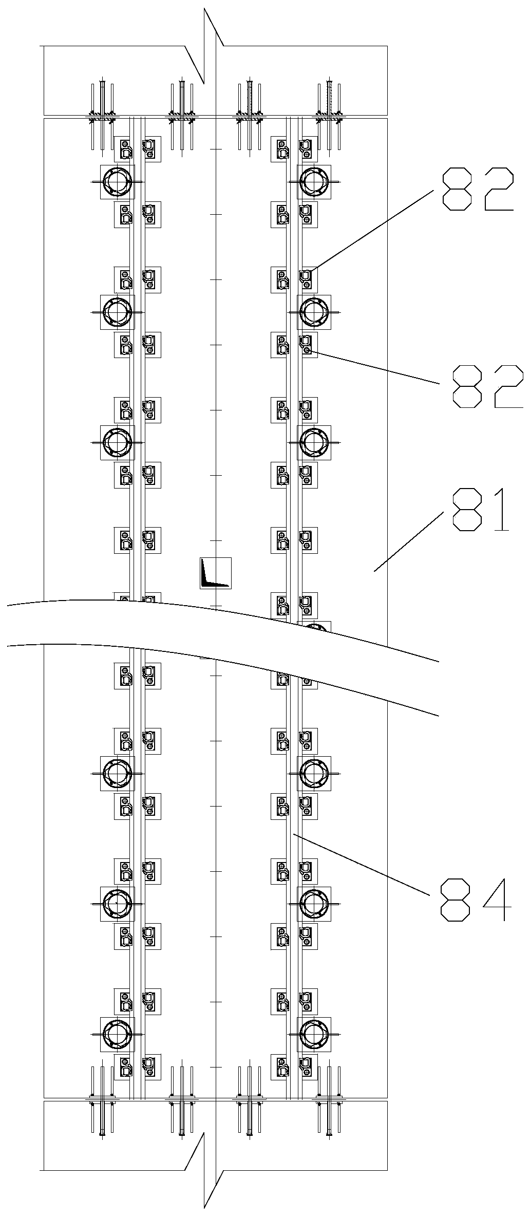
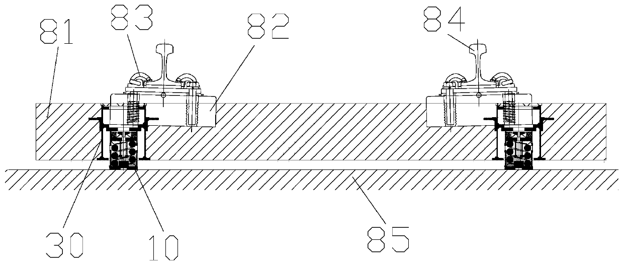
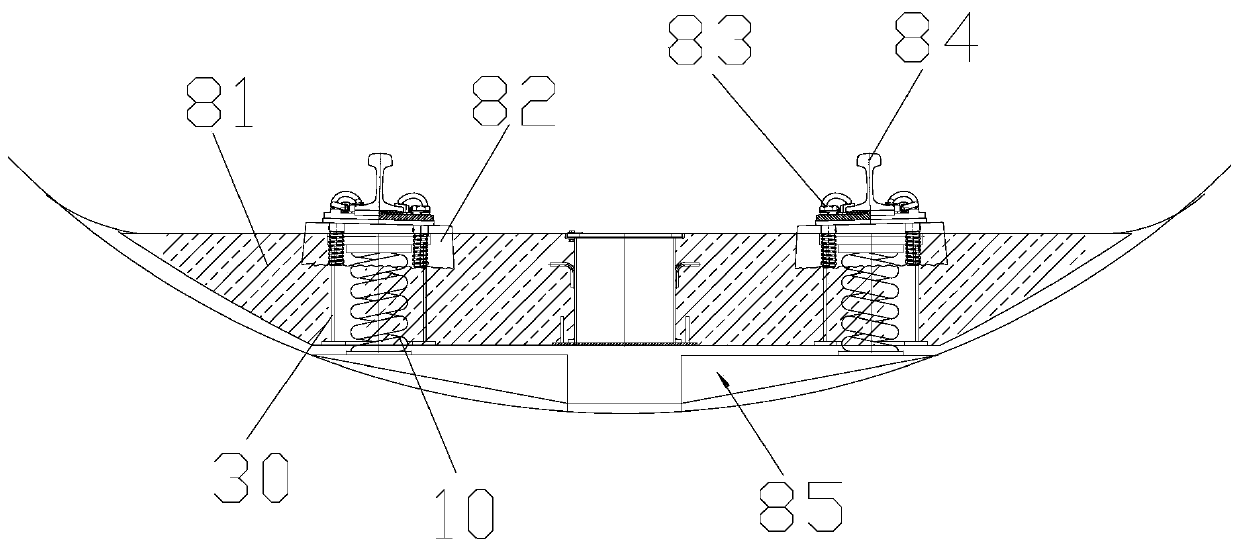
[0047] like Figure 1 to Figure 7 As shown, Embodiment 1 of the present invention provides a track system, including a floating plate 81, a rail platform 82, a fastener assembly 83, a steel rail 84 and a vibration isolator with high static and low dynamic stiffness characteristics, and the rai...


PUM


Abstract

The invention provides a rail system. The rail system comprises a floating plate, supporting rail tables, fastening assemblies, steel rails and a vibration isolator with high hydrostatic pressure and low dynamic stiffness characteristic, wherein the supporting rail tables are poured on the floating plate; the steel rails are fixed on the supporting rail tables through the buckle assemblies; a positive stiffness assembly of the vibration isolator comprises a seat body and first elastic parts arranged in a cavity of the seat body, and the bottom of the seat body is arranged on a base; a supporting part abuts against the upper ends of the first elastic parts; floating parts are poured in the floating plate, and a gap is formed between the floating plate and the base; a negative stiffness assembly comprises elastic parts and bearing parts which are mutually matched, the elastic parts are connected to the supporting part and / or the floating parts, and the bearing parts are connected to the seat body; when the floating parts bear load, the direction of acting force, applied to the bearing parts, by the elastic parts is set in an inclined mode or perpendicularly relative to the direction of elastic force of the first elastic parts. With the adoption of the technical scheme, the rail system can improve vibration isolating frequency range and low-frequency vibration damping effect of the vibration isolator and the rail system, and controls dynamic displacement while a train passes through the rail system.

Description

technical field [0001] The invention relates to the technical field of vibration reduction and noise reduction of a track system, in particular to a track system. Background technique [0002] Low-frequency vibration isolation of rail systems is a major research hotspot and difficulty in the field of rail transit vibration isolation. Structural vibration control can be divided into passive control, active control, semi-active control and hybrid control according to whether external energy input is required. Active control vibration isolation and semi-active control vibration isolation technologies are used to isolate low-frequency vibrations well, but their structures are complex. , takes up a lot of space, has high manufacturing costs, requires external energy, and has problems such as instability and electromagnetic pollution. In contrast, the traditional passive vibration isolation structure is simple, easy to implement, reliable, and does not consume extra external ener...

Claims


Application Information

Patent Timeline
Patent Type & Authority Applications(China)
IPC IPC(8): E01B1/00E01B19/00
CPCE01B1/002E01B19/003E01B2204/09
Inventor 杜香刚刘韦施成刘伟斌王继军肖俊恒
Owner RAILWAY ENG RES INST CHINA ACADEMY OF RAILWAY SCI
Why Eureka
Try Eureka