Linkage control type handheld washing machine

A cleaning machine, control technology, applied in pump control, machine/engine, liquid variable volume machinery, etc., can solve problems such as affecting the stability of the other hand, affecting the operating experience, etc., to improve the use experience, The effect of reducing the difficulty of operation and improving the comfort of use

Active Publication Date: 2019-09-27
SUMEC HARDWARE & TOOLS
View PDF6 Cites 3 Cited by
  • Summary
  • Abstract
  • Description
  • Claims
  • Application Information

AI Technical Summary

Problems solved by technology

It can be seen that if one hand needs to operate multiple buttons, it will affect the operating experience, and it will also affect the holding stability of the other hand.

Method used


Image

  • Linkage control type handheld washing machine
  • Linkage control type handheld washing machine
  • Linkage control type handheld washing machine

Examples


Embodiment 1

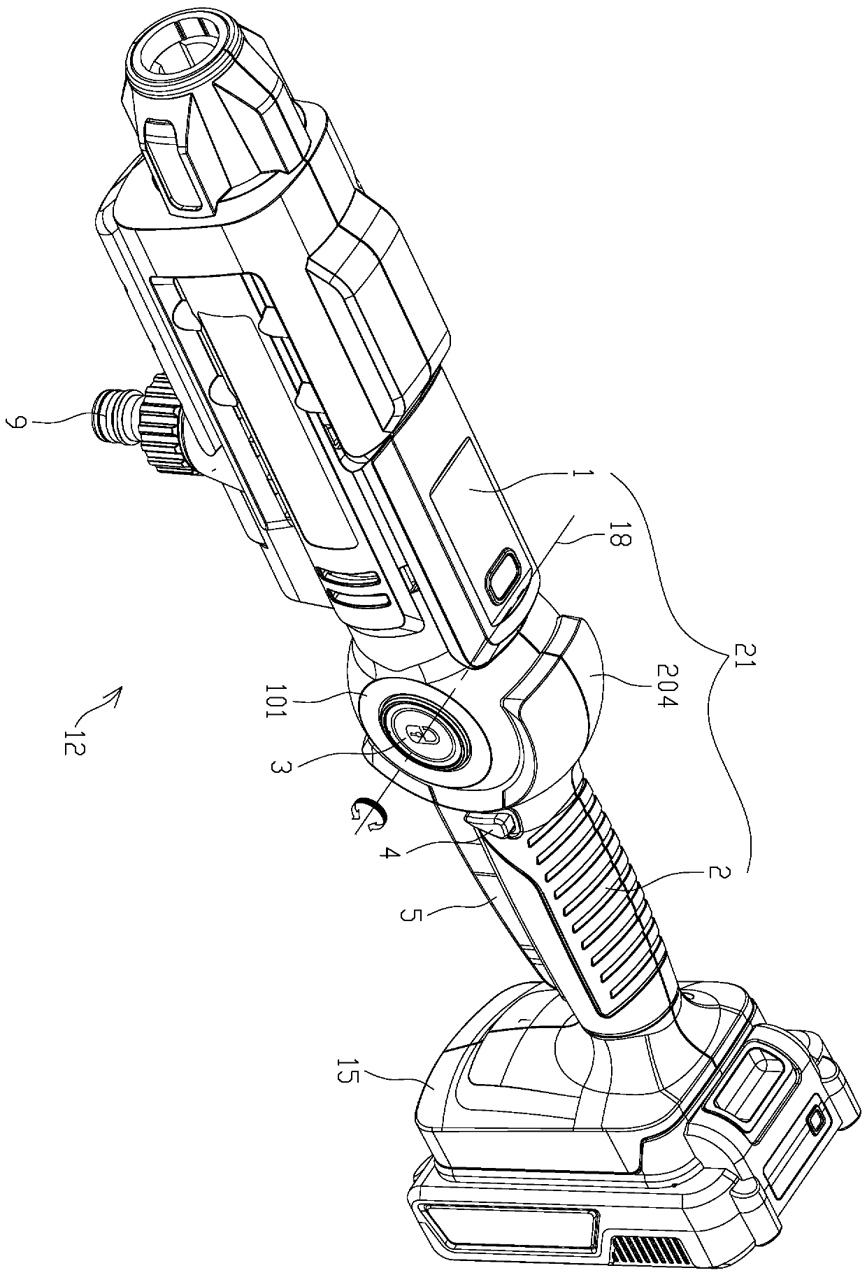
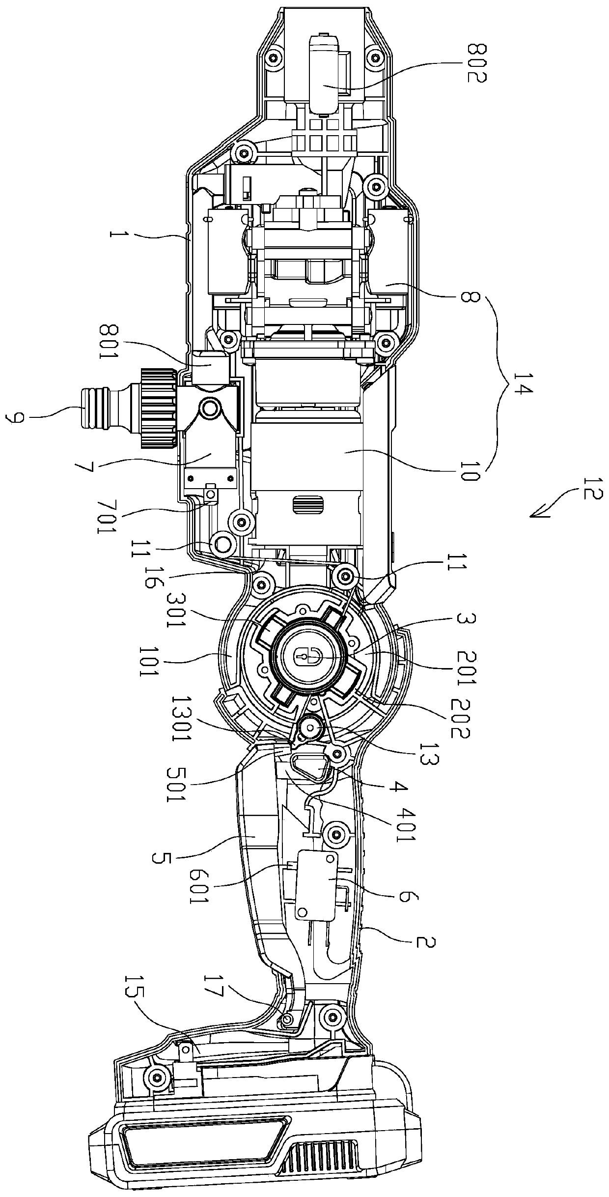
[0050] Such as figure 1 , 2 , 3, 6, 7, 8, 9, and 10, a linkage control type hand-held washing machine 12 includes: a housing 21, an adjustment switch 3, a reset member I20, a battery pack 15, a motor pump unit 14, a water inlet Valve 7, control trigger 5, switch 6, flexible traction member 16, guide member I11, rotating member 13, safety switch 4 and reset member II.

[0051] The casing 21 includes a main casing 1 and a handle 2. The main casing 1 is used to accommodate the motor pump unit 14, the water inlet valve 7 and related components. The handle 2 is used as a handle for people to hold and is used to accommodate the switch 6 and related components. Both the main casing 1 and the handle 2 are of half-shell structure, and are connected by screws so as to form a cavity inside them for accommodating components.

[0052] The main casing 1 has a rear connecting portion 101 , and the handle 2 has a front connecting portion 201 forming a rotational connection with the rear conne...

Embodiment 2

[0067] Such as Figure 11 As shown, the difference between the present embodiment and the first embodiment is that the two ends of the receiving portion I103 of the main casing 1 respectively pass through the rear connecting portion 101 along the direction of the axis 18 to form two operation holes respectively accommodating the ends of the adjustment switch 3 105. At this time, both ends of the regulating switch 3 can be pressed by the user so that the regulating switch 3 can slide between its first position and its second position, and the switch between the two positions does not need to be completed by the reset member I20. In this embodiment, the adjusting switch 3 can also be used as a pivot for the rotational connection between the main casing 1 and the handle 2 .

Embodiment 3

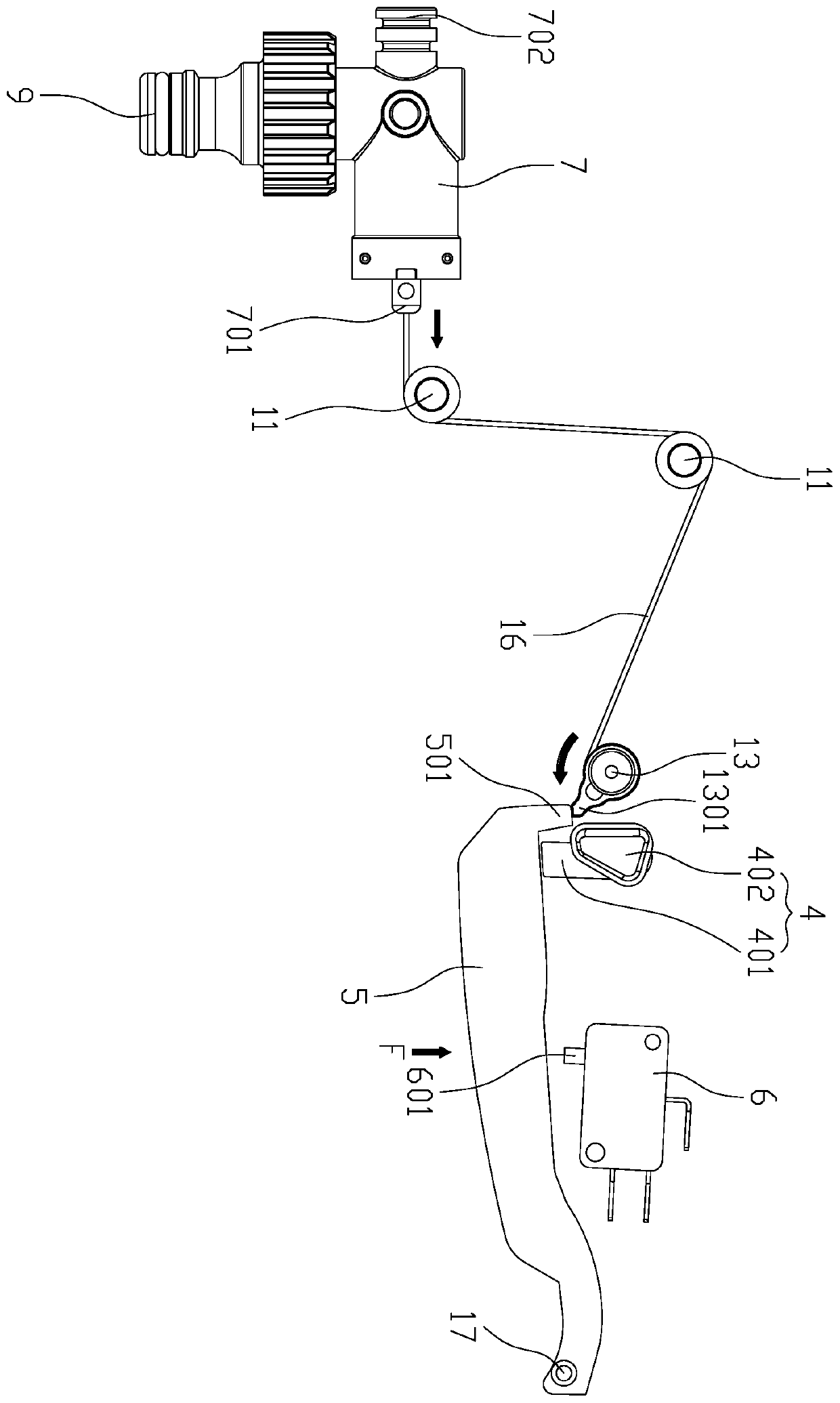
[0069] Such as Figure 4 As shown, the difference between this embodiment and the first embodiment is that the rotating member 13 is a roller with a gear tooth portion I1302, and correspondingly, the control trigger 5 has a gear tooth portion II502 meshing with the gear tooth portion I1302. When the control trigger 5 rotates around the pivot 17 , the turret 13 rotates with the control trigger 5 under the meshing effect of the gear tooth part II502 and the gear tooth part I1302 so as to realize the traction of the flexible traction member 16 to the spool 701 .


PUM


Abstract

The invention discloses a linkage control type handheld washing machine comprising a motor pump unit, a water inlet valve, a control trigger, a switch and a shell. The motor pump unit comprises a pump and a motor driving the pump. The water inlet valve comprises a water inlet, a water outlet and a valve element arranged in a sliding manner. Operation of the motor pump unit is controlled through the control trigger. The switch comprises a contact controlling start and stop of the motor. The motor pump unit, the water inlet valve and the switch are contained in the shell. The control trigger is movably arranged on the shell. The motor is connected with the switch through a drive circuit. The pump comprises a high-pressure water outlet and a pump water inlet. The water outlet is connected with the pump water inlet. By means of the linkage control type handheld washing machine, linkage control of the water inlet valve and the motor pump unit can be achieved, a machine body can also be folded on this basis so that the holding posture can be adjusted, and the comfort degree of users is improved.

Description

technical field [0001] The invention belongs to the technical field of hand-held washing machines, and in particular relates to a linkage control type hand-held washing machine. Background technique [0002] The cleaning machine is a kind of equipment that uses water or a mixed solution added with cleaning agent as the cleaning medium, and uses high-pressure water flow to clean the surface of objects. The cleaning machine can be used to clean cars, courtyards, floors, railings, doors and windows, etc. It is more efficient and effective to use. Convenience, its main components are spray gun and host, host includes motor, pump and battery or external power cord, spray gun and host are connected through water inlet pipe, spray gun is responsible for forming different shapes of water flow according to actual needs, and host is responsible for water from municipal tap water Or convert it into a high-pressure water flow in a bucket and send it to the spray gun. The common one is t...

Claims


Application Information

Patent Timeline
Patent Type & Authority Applications(China)
IPC IPC(8): F04B17/03F04B49/06F04B49/22B08B3/02B08B13/00
CPCB08B3/02B08B13/00F04B17/03F04B49/06F04B49/22
Inventor 刘楷林有余黄云
Owner SUMEC HARDWARE & TOOLS
Why Eureka
Try Eureka