Large-current pin structure of vertical resonant transformer

A resonant transformer, high current technology, applied in the direction of transformer/inductor shell, transformer/inductor core, transformer/inductor components, etc., can solve complex structure, shortened safety distance, and limited winding area question

Inactive Publication Date: 2019-09-27
YUJING TECH CO LTD
View PDF7 Cites 5 Cited by
  • Summary
  • Abstract
  • Description
  • Claims
  • Application Information

AI Technical Summary

Problems solved by technology

[0004] 1. The structure of the insulating shell such as the shell cover is too complicated. Although it has a good insulating effect, in order to meet the demands of miniaturization and light weight of the transformer, the structure of these insulating shells must conform to the structure of the existing transformer, resulting in a rather complicated structure. , Moreover, the fitting of the insulating shell and the wire frame takes up a considerable space, which limits the extremely precious winding area
[0005] 2. The demand for miniaturization of the transformer mainly corresponds to the miniaturization of electronic products. Among them, the area of ​​the circuit board is increasingly miniaturized. In the above-mentioned patents, the pins of the transformer are arranged in two rows

Method used


Image

  • Large-current pin structure of vertical resonant transformer
  • Large-current pin structure of vertical resonant transformer
  • Large-current pin structure of vertical resonant transformer

Examples


Embodiment Construction

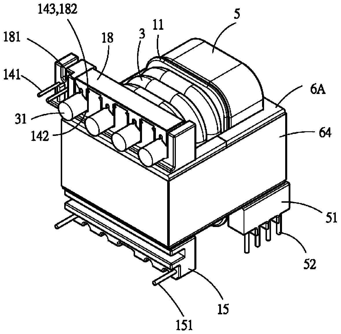
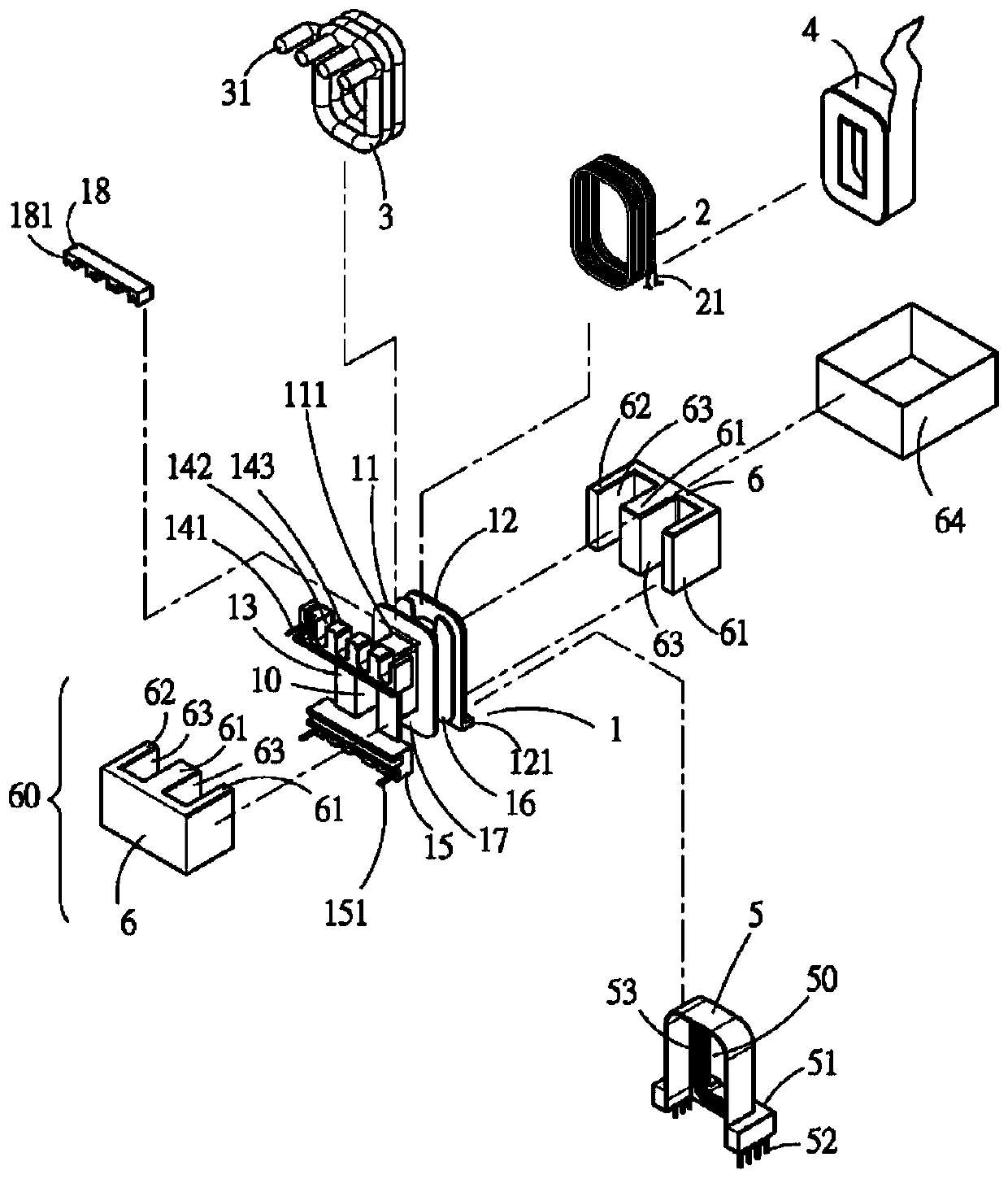
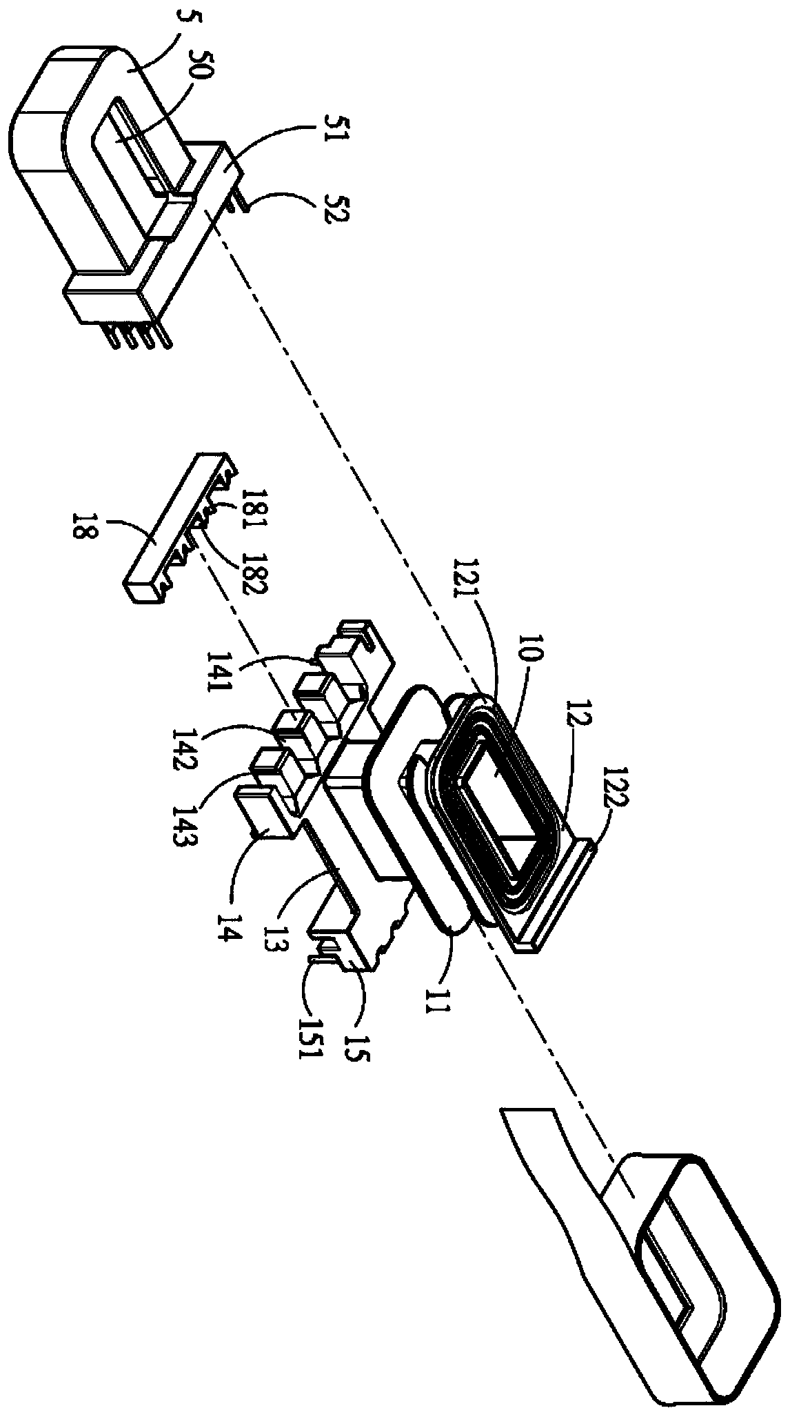
[0032] see Figure 1 to Figure 3 As shown, it can be seen that the structure of the present invention mainly includes: a frame 1, a first coil 2, a second coil 3, an insulating layer 4, a shell 5 and a core group 6, wherein:

[0033] There is a central hole 10 in the wire frame 1, a first partition plate 11 is arranged on the wire frame 11, a second partition plate 12 and a third partition plate 13 are respectively arranged at both ends, and the second partition plate The surface of 12 is provided with a plurality of first ring parts 121; the third partition plate 13 has a connection part 14 on one side, and a plurality of control pins 141 are provided on the connection part 14 side, and a plurality of control pins 141 are provided on the connection part 14. The grooves 142, these grooves 142 have a joint portion 143 near the opening, these grooves 142 are used for a fixed block 18 to be assembled, and the fixed block 18 extends with a large number of positioning pins 181, and...


PUM


Abstract

The invention discloses a large-current pin structure of a vertical resonant transformer. A first partition plate is arranged on a coil holder, and a second partition plate and a third partition plate are arranged at the two sides of the coil holder; a wiring part is arranged on the third partition plate, and a first coil is wound around a first wire duct formed between the first partition plate and the second partition plate; and a second coil is wound around a second wire duct formed between the first partition plate and the third partition plate. An insulating layer wraps the first coil and the first partition plate and wraps the root of the first partition plate, so that the creepage distance between the first coil and the second coil is increased. A shell cover is disposed on the second partition plate in a sleeving manner, covers the first coil and extends to the first partition plate; the first coil is connected to a connection terminal of the shell cover. The connection terminal is connected with a circuit mainboard, and the second coil extends to a wiring part and is connected to the circuit mainboard through an adapter card to increase the distance between the wiring part and the connection terminal; the adapter card can adopt double panels to greatly reduce the circuit impedance, thereby meeting the requirements of adopting the double panels and passing the safety regulation for the circuit mainboard, and reducing the manufacturing cost.

Description

technical field [0001] The invention relates to a vertical resonant transformer, in particular to a high-current pin structure of a vertical resonant transformer that simplifies the circuit layout of the main board, naturally increases the distance between the primary side and the secondary side, and increases the insulation and shielding effect. Background technique [0002] Common vertical resonant transformers, such as China Taiwan Invention Patent Bulletin No. I463508 "Improved Structure of Transformer", use a frame to cover at least part of a preset iron core group, and make the iron core group have a Through the magnetic conduction circuit of the wire frame, a wire slot and at least one connecting portion protruding outward are provided on the outer peripheral side of the wire frame, and a plurality of grooves with lateral openings are arranged on the connecting portion, and a coil is wound on In the wire groove of the wire frame, the aforementioned coils have at least...

Claims


Application Information

Patent Timeline
IPC IPC(8): H01F27/30H01F27/32H01F27/26H01F27/24H01F27/29H01F27/02
CPCH01F27/02H01F27/24H01F27/266H01F27/29H01F27/306H01F27/324
Inventor 杨森泰
Owner YUJING TECH CO LTD
Why Eureka
Try Eureka