
A plasmonic device

A plasmon, metal grating technology, applied in measuring devices, optical components, optics, etc., to avoid interference with background signals

Inactive Publication Date: 2019-09-27
爱克斯福德影像公司
View PDF15 Cites 2 Cited by
  • Summary
  • Abstract
  • Description
  • Claims
  • Application Information

AI Technical Summary

Problems solved by technology

Detection and observation of the plasma membrane remains a challenge

Method used


Image

  • A plasmonic device
  • A plasmonic device
  • A plasmonic device

Examples


Embodiment Construction

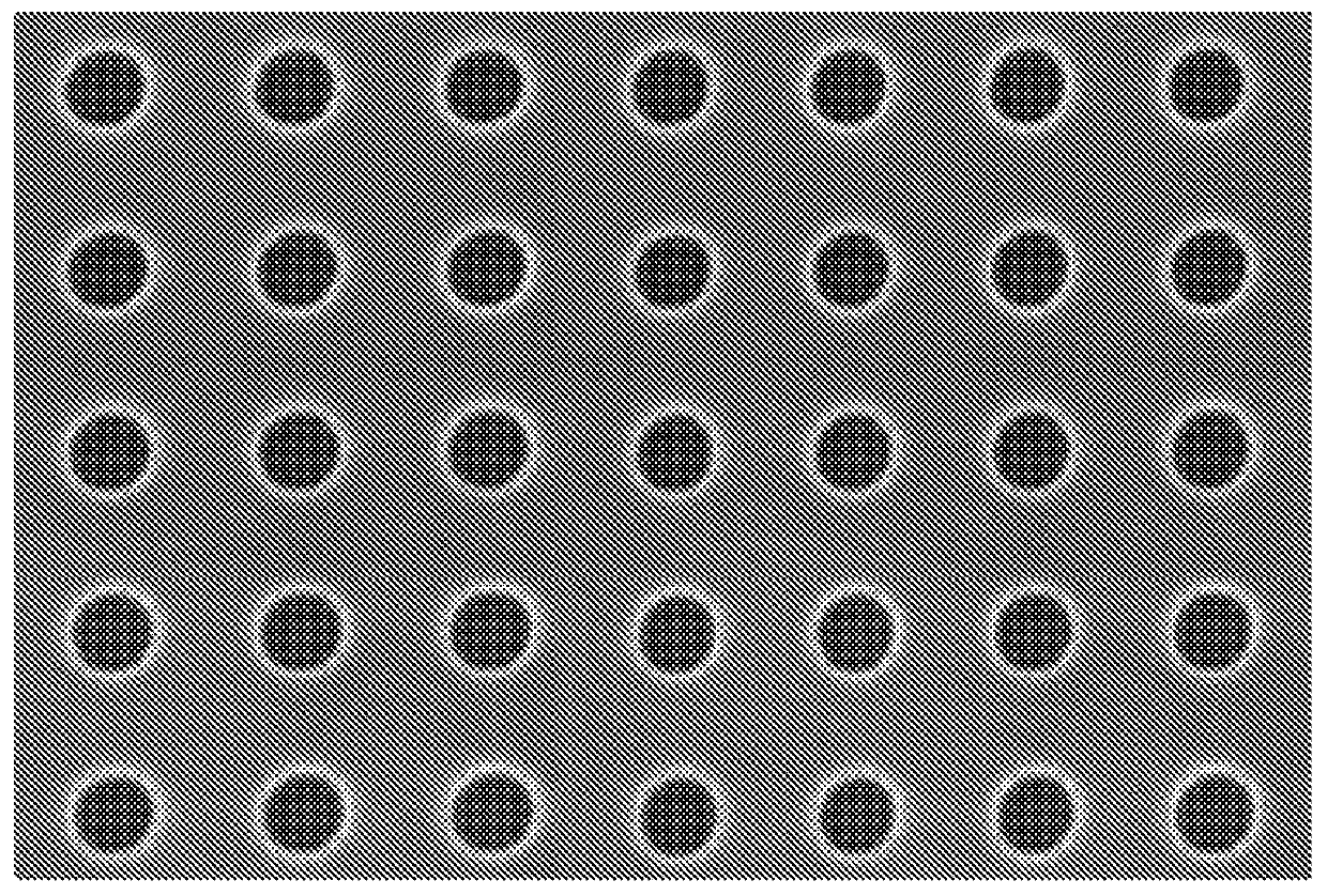
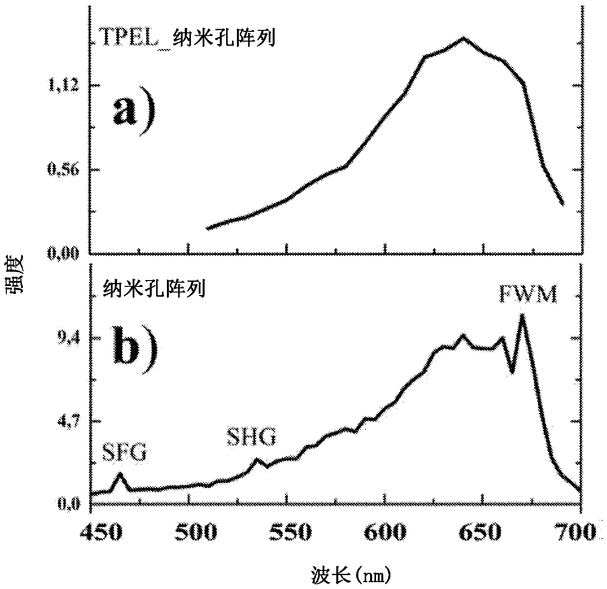
[0053] Different embodiments of the plasmonic device according to the present invention are described below with reference to FIGS. 1-5 .

[0054] The present invention relates to surface plasmon (SP) structures with well-defined features at predetermined locations on a substrate for enhancing the properties of materials used in linear and nonlinear spectroscopy, microscopy, and imaging techniques such as SERS, Optical signals generated by the enhanced optical process used in SECARS and SRS.

[0055] Figures 1A-1B and Figures 2A-2B have been discussed in more detail in connection with the Background section herein.

[0056] An exemplary embodiment of the SP structure of the present invention is as Figure 3A shown. According to an embodiment of the invention, the plasmonic device can be constructed in several ways, but it advantageously comprises at least one metal layer 003 and a one-dimensional metal grating 004 made of metal strips. Typically, the device is constructed on...


PUM

PropertyMeasurementUnit
thicknessaaaaaaaaaa
thicknessaaaaaaaaaa
thicknessaaaaaaaaaa

Abstract

A plasmonic device (100) to enhance optical processes in samples lying on or in the proximity of the surface of the device comprises a substrate (001) and a plasmonic structure (008). The plasmonic structure (008) comprises advantageously a full metal layer (003) and a metal grating (004) in connection with the full metal layer (003). In addition, the plasmonic device (100) may comprise an optional adhesion layer (002) between the substrate (001) and the plasmonic structure (003, 004) and / or, an optional protective layer () above the full metal layer (003) or metal grating (004).

Description

technical field [0001] The present invention relates to surface plasmon (SP) devices to enhance optical processes in samples in the vicinity of the device. In particular, the present invention relates to the design and fabrication of plasmonic devices for linear and nonlinear microscopy and spectroscopy applications in fields such as physics, chemistry, biology, bioimaging and medical diagnostics. Background technique [0002] Currently, many optical measurement techniques are used for imaging or characterizing materials, structures, cells and tissues, eg in physics, chemistry and biology. In many of these techniques, the sample to be studied is placed on or near the surface of a suitable substrate material. Many technologies also use light with known properties, such as lasers with defined wavelengths. To improve upon the state of the art in these cases, the substrate on which the sample is placed can incorporate features to enhance the measurement process, such as the in...

Claims


Application Information

Patent Timeline
Patent Type & Authority Applications(China)
IPC IPC(8): G02B5/18G02B5/00
CPCG02B5/008G02B5/1809G01N21/554
Inventor 纳贾拉詹·苏布拉马尼亚姆马尔库·索潘恩埃利娜·伊科宁安蒂·伊索迈基西蒙·普菲斯特雷尔
Owner 爱克斯福德影像公司
Learn More