Field-enhancing device

A technology for enhancing devices and structures, applied in measuring devices, nanotechnology, instruments, etc., can solve problems such as detailed visualization obstacles

Inactive Publication Date: 2020-06-30
爱克斯福德影像公司
View PDF12 Cites 0 Cited by
  • Summary
  • Abstract
  • Description
  • Claims
  • Application Information

AI Technical Summary

Problems solved by technology

However, when zoomed in to cells or tissues where essentially all molecules and most subcellular organelles are smaller than this lateral and depth resolution, it becomes an obstacle to visualizing these structures in detail

Method used


Image

  • Field-enhancing device
  • Field-enhancing device
  • Field-enhancing device

Examples


Embodiment approach

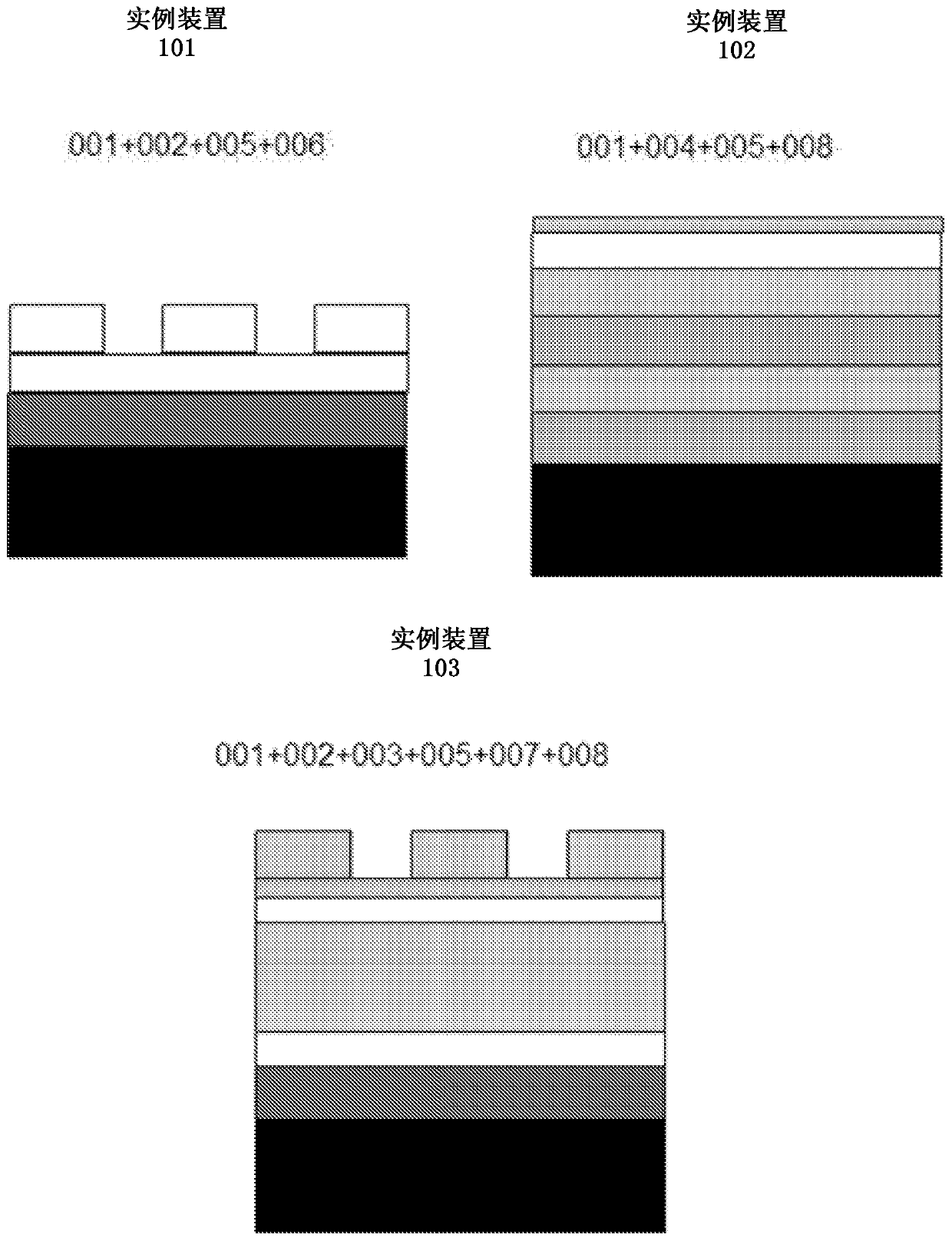
[0073] exist image 3 Three exemplary embodiments of the invention are shown in: SP version with metal grating (top left, device 101), TP version with DBR mirror (top right, device 102), and metal mirror structure and dielectric TP version of the grating (bottom, device 103).

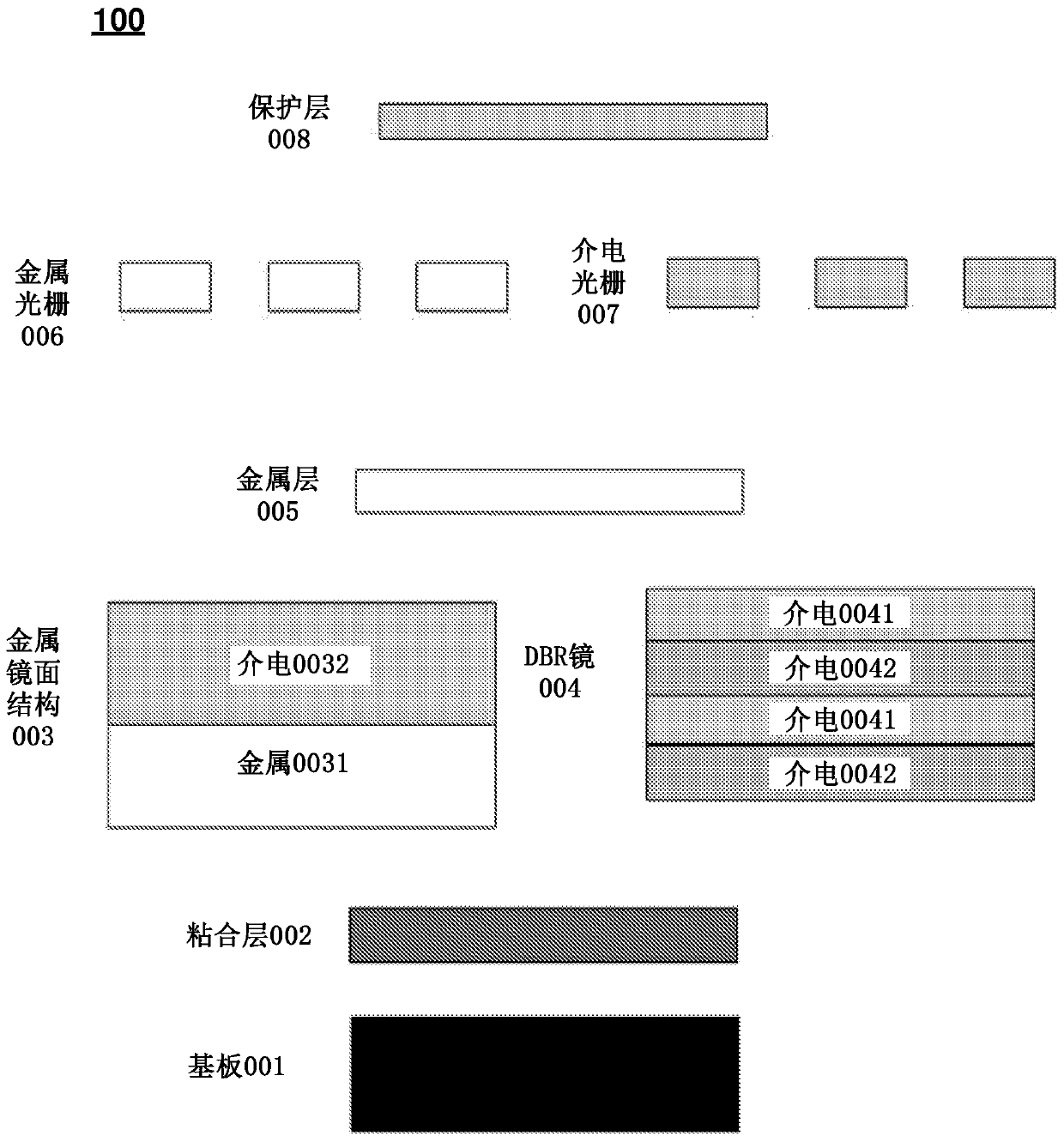
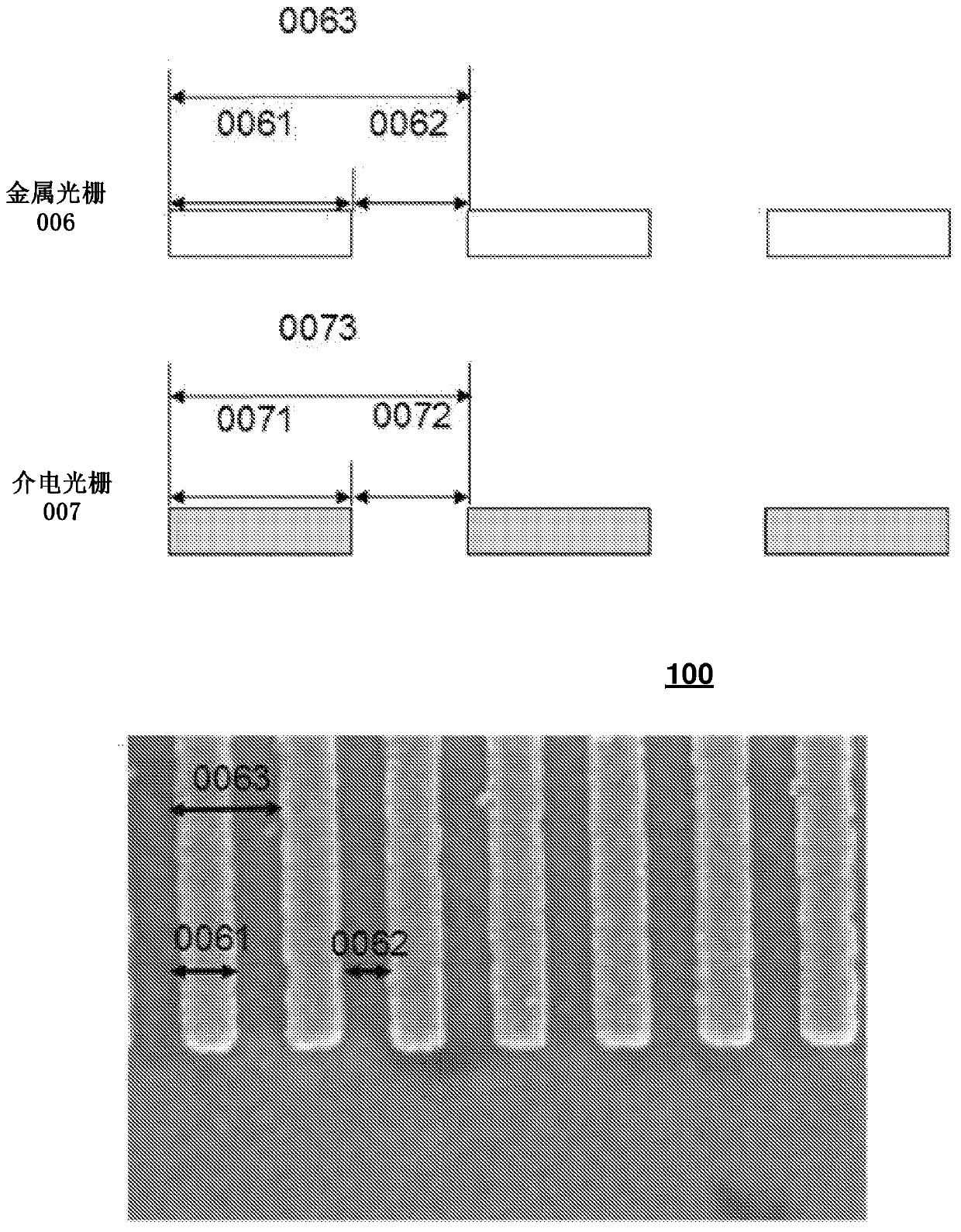
[0074] In another advantageous embodiment of the invention, the device comprises a substrate, an adhesive layer, a metallic mirror structure with a dielectric layer and a dielectric grating. The device may then also include a protective layer. This embodiment of the device uses the diffraction grating effect. In this structure, the metal mirror can also be replaced by a DBR mirror. In this case, an additional dielectric layer can also be added between the DBR mirror and the dielectric grating.

[0075] Advantageously, this version of the device can be used with both TE and TM mode lasers.

[0076] Various embodiments of the device are well suited and stable to be adjacent to various media such as w...


PUM

PropertyMeasurementUnit
thicknessaaaaaaaaaa
thicknessaaaaaaaaaa
thicknessaaaaaaaaaa

Abstract

A field-enhancing device (100) comprises at least one metal layer (005) or a metal grating (006) consisting of metal stripes or a dielectric grating (007). Usually the device is constructed on some substrate (001). The adhesive layer (002) is advantageous when the next layer is metallic, but is not needed with dielectric layers. The next layers to be constructed form a mirror structure that can also be omitted for simple field enhancing device constructs. The mirror structure can be either a metal mirror structure (003) or a distributed Bragg reflector structure (DBR) (004). The next layer isthe thin metal layer (005). This layer can be covered with a 1-D metal grating (006) consisting of metal stripes or with a dielectric grating (007) having similar geometry. The structure can also be fabricated without metals when dielectric grating (007) is used as the field-enhancing part. Finally, a protective layer (008) can be added on top of the structure.

Description

technical field [0001] The present invention relates to an electric field enhancing device that enhances optical processing in a sample in the vicinity of the device. In particular, the present invention relates to the design and fabrication of field-enhancing devices for linear and nonlinear microscopy and spectroscopy applications, eg, in the fields of physics, chemistry, biology, bioimaging and medical diagnostics. Background technique [0002] Today, many optical measurement techniques are used to image or characterize materials, structures, cells and tissues in physics, chemistry and biology. In many of these techniques, the sample to be studied is placed on the surface of a suitable substrate material. Many technologies also use light with known properties, such as laser light with a predetermined wavelength. To improve the state of the art in these cases, the substrate on which the sample is placed may contain features to enhance measurement processing. [0003] Th...

Claims


Application Information

Patent Timeline
Patent Type & Authority Applications(China)
IPC IPC(8): G02B5/00G02B5/18G01N21/552G01N21/64G01N21/65B82Y30/00H01L21/64G01J3/18
CPCB82Y20/00B82Y30/00G01N21/255G01N21/553G01N21/636G01N21/648G01N21/658G01N21/774G01N2021/653G02B5/008G02B5/0858G02B21/0076G02B21/34G02B27/425G02B2207/101G02B5/085G02B5/1861
Inventor 纳加拉詹·苏布拉马尼亚姆马尔库·索帕宁埃利娜·伊科宁安蒂·伊索迈基西蒙·普菲斯特雷尔
Owner 爱克斯福德影像公司
Why Eureka
Try Eureka