Supercharge Your Innovation With Domain-Expert AI Agents!

Milling clamp

A fixture and milling technology, applied in the field of fixture tooling, can solve problems such as difficult positioning, low efficiency, and difficulty in ensuring concentricity, and achieve the effects of ensuring concentricity, high repeat positioning accuracy, and improving processing efficiency and processing accuracy

Pending Publication Date: 2019-10-01
TIANJIN ZHENGTIAN MEDICAL INSTR CO LTD
View PDF0 Cites 1 Cited by
  • Summary
  • Abstract
  • Description
  • Claims
  • Application Information

AI Technical Summary

Problems solved by technology

[0003] In view of the deficiencies in the prior art, the purpose of the present invention is to provide a milling fixture to solve the problems of difficult positioning, difficulty in ensuring concentricity, low repeat positioning accuracy and low efficiency in the prior art

Method used


Image

  • Milling clamp
  • Milling clamp
  • Milling clamp

Examples


Embodiment Construction

[0034] A milling fixture of the present invention will be described in detail below in conjunction with the drawings and embodiments of the specification:

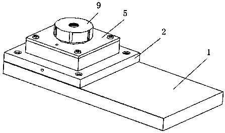
[0035] Such as Figure 1-5 As shown, this embodiment provides a milling fixture, which includes a base 1 , a base 2 , an expanding core 3 , a moving part 4 and a driving assembly. The base 2 is installed on the base 1, specifically, the base 1 is provided with a positioning groove 11, and the base 2 is provided with a positioning protrusion 21, and the positioning protrusion 21 cooperates with the positioning groove 11. The side of the positioning groove 11 is arranged obliquely, and the opening area of ​​the positioning groove 11 is larger than the area of ​​its bottom surface, which facilitates the installation and positioning of the base 2 on the base 1 . In addition, the base 2 and the base 1 are also connected by screws.

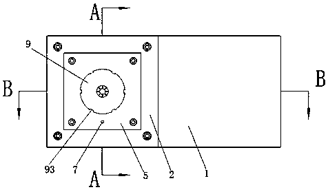
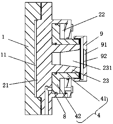
[0036] Such as image 3 and 4 As shown, the base 2 is provided with an annular first cavity ...


PUM


Abstract

The invention discloses a milling clamp, and relates to the technical field of clamp tools. The milling clamp comprises a base, an expansion core, a moving piece and a driving assembly, wherein an annular first cavity is formed in the base, a boss is arranged in the middle of the first cavity, a second cavity is formed in the boss, the second cavity is in a frustum shape, the open end of the second cavity is a larger end, the expansion core is in a frustum shape and can be slidably arranged in the second cavity, a central hole is formed in the expansion core, the central hole and the second cavity are coaxially arranged, the diameter of the central hole is reduced or increased when the expansion core slides upwards in the axial direction of the second cavity in a reciprocating manner, themoving piece is slidably arranged in the first cavity and can drive the expansion core to move synchronously in the axial direction of the second cavity, and the driving assembly is used for driving the moving piece to move in the axial direction of the second cavity in a reciprocating mode. According to the milling clamp, the concentricity of parts can be ensured, the repeated positioning precision is high, and the machining efficiency and the machining precision are improved.

Description

technical field [0001] The invention belongs to the technical field of jigs and fixtures, and in particular relates to a milling jig. Background technique [0002] Now processing parts with turning process and milling process, usually use three-jaw chuck or vise to clamp the workpiece for processing. However, when the three-jaw chuck or flat-nose pliers clamp the parts, it is often impossible to guarantee the shape and position tolerances such as concentricity, coaxiality, symmetry, and verticality, and it is difficult to align the workpiece when installing and clamping, and it is easy to pinch the surface of the workpiece. low. Therefore, it is urgent to design a milling fixture to meet the processing requirements. Contents of the invention [0003] In view of the deficiencies in the prior art, the purpose of the present invention is to provide a milling fixture to solve the problems in the prior art of difficult positioning, difficult to ensure concentricity, low repea...

Claims


Application Information

Patent Timeline
IPC IPC(8): B23Q3/08
CPCB23Q3/08B23Q2703/04
Inventor 徐西营鲍野刘三
Owner TIANJIN ZHENGTIAN MEDICAL INSTR CO LTD
Features
  • R&D
  • Intellectual Property
  • Life Sciences
  • Materials
  • Tech Scout
  • Unparalleled Data Quality
  • Higher Quality Content
  • 60% Fewer Hallucinations
Learn More