A laser micro-hole processing method with dynamic adjustment of multi-focus

A technology of microhole processing and laser processing, which is applied in the direction of metal processing equipment, laser welding equipment, manufacturing tools, etc., can solve the problem that it is difficult to meet the processing requirements of high efficiency, high quality and high depth-to-diameter ratio of microholes, and limit the efficiency of microhole processing It can process the micro-hole depth-to-diameter ratio and lack of flexibility in laser processing methods, etc., to improve the micro-hole processing depth-to-diameter ratio and processing efficiency, realize the adjustable diameter and focal length, and improve the effect of micro-hole processing depth-to-diameter ratio

Active Publication Date: 2021-05-25
GUANGDONG UNIV OF TECH
View PDF7 Cites 0 Cited by
  • Summary
  • Abstract
  • Description
  • Claims
  • Application Information

AI Technical Summary

Problems solved by technology

[0003] In the prior art, there are mainly the following problems: 1. With the increase of the microhole processing depth, the loss of laser energy and the difficult-to-spray material slag limit the microhole processing efficiency and the depth-to-diameter ratio of the machinable microholes; 2. , With the diversification of materials and microhole processing requirements, the lack of flexible laser processing methods makes it difficult to meet the processing requirements of high efficiency, high quality, and high depth-to-diameter ratio for microholes

Method used


Image

  • A laser micro-hole processing method with dynamic adjustment of multi-focus
  • A laser micro-hole processing method with dynamic adjustment of multi-focus
  • A laser micro-hole processing method with dynamic adjustment of multi-focus

Examples


Embodiment 1

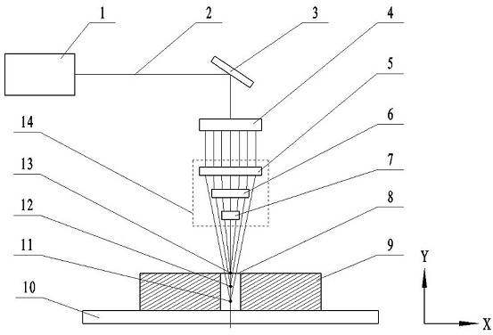
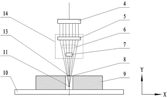
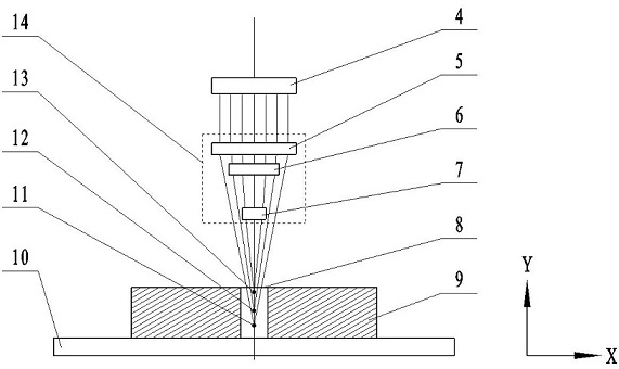
[0025] This embodiment provides a laser microhole processing method with dynamic adjustment of multi-focus. An ultrafast laser with a pulse width of 290 fs and a power of 10 W is used to process silicon nitride ceramic microholes with a thickness of 5 mm and an aperture of 200 μm. The surface of the silicon nitride ceramic workpiece 9 to be processed is ground and polished, fixed on the working platform 10, and the working platform 10 is moved so that the silicon nitride ceramic workpiece 9 is located under the laser processing system. Before laser processing, turn on the laser processing system and use the third focusing mirror 7 to complete the laser focusing on the surface of the silicon nitride ceramic workpiece 9, then turn off the laser processing system. During laser processing, the silicon nitride ceramic workpiece 9 is first moved and the micro-hole processing area 8 is selected to be located below the dynamic focusing lens group 14 of the laser processing system, and ...

Embodiment 2

[0027] This embodiment provides a laser microhole processing method with dynamic adjustment of multi-focus. An ultrafast laser with a pulse width of 10 ps and a power of 20 W is used to process alumina ceramic microholes with a thickness of 3 mm and an aperture of 100 μm. The surface of the alumina ceramic workpiece 9 to be processed is ground and polished, fixed on the working platform 10, and the working platform 10 is moved so that the alumina ceramic workpiece 9 is located under the laser processing system. Before laser processing, turn on the laser processing system and use the third focusing mirror 7 to complete the laser focusing on the surface of the alumina ceramic workpiece 9, and then turn off the laser processing system. During laser processing, the alumina ceramic workpiece 9 is first moved and the micro-hole processing area 8 is selected to be located below the dynamic focusing lens group 14 of the laser processing system, and then the laser processing system is t...

Embodiment 3

[0029]This embodiment provides a laser microhole processing method with dynamic adjustment of multi-focus. An ultrafast laser with a pulse width of 290 fs and a power of 10 W is used to process silicon nitride ceramic microholes with a thickness of 5 mm and an aperture of 200 μm. The surface of the silicon nitride ceramic workpiece 9 to be processed is ground and polished, fixed on the working platform 10, and the working platform 10 is moved so that the silicon nitride ceramic workpiece 9 is located under the laser processing system. Before laser processing, turn on the laser processing system and use the third focusing mirror 7 to complete the laser focusing on the surface of the silicon nitride ceramic workpiece 9, then turn off the laser processing system. During laser processing, the silicon nitride ceramic workpiece 9 is first moved and the micro-hole processing area 8 is selected to be located below the dynamic focusing lens group 14 of the laser processing system, and t...


PUM


Abstract

The invention provides a laser microhole processing method with dynamic multi-focus adjustment, which comprises the following steps: grinding and polishing the surface of the workpiece, fixing it on the work platform, and completing the laser focusing on the surface of the workpiece before laser processing; during laser processing, first moving the workpiece and The selected micro-hole processing area is located below the dynamic focus lens group of the laser processing system; the laser beam enters the dynamic focus lens group in turn to form a plurality of micro-hole processing areas with focal points on the workpiece; each focusing lens in the dynamic focus lens group can move along the X , and move in the Y direction to adjust the number of focal points and the relative position of the focal points respectively, and then complete the micro-hole processing. The invention forms multiple focal points in the microhole processing area of ​​the material by introducing at least two focusing mirrors, and can dynamically adjust the relative positions of the at least two focusing mirrors to realize the adjustable focus spot diameter and focal length, which can improve the microhole processing efficiency At the same time, improve the machinable micro-hole depth-to-diameter ratio and processing quality.

Description

technical field [0001] The invention belongs to the technical field of laser processing, and in particular relates to a laser microhole processing method for dynamically adjusting multi-focus. Background technique [0002] Laser micro-hole processing technology can quickly remove materials through the focused high-energy laser beam without tool wear. It has advantages that traditional processing technologies cannot match. It has been widely used in aerospace, electronic information, rail transportation and other fields, and has developed rapidly. As the depth of microhole processing increases, the energy loss of the laser and the difficult-to-remove slag remaining in the microhole severely limit the efficiency of microhole processing and the ratio of the depth to diameter of the microhole that can be processed. Ordinary focused single-focus laser processing technology It has been unable to meet the ever-increasing requirements of micro-hole processing. The emergence of new ...

Claims


Application Information

Patent Timeline
Patent Type & Authority Patents(China)
IPC IPC(8): B23K26/382B23K26/064
CPCB23K26/0648B23K26/382
Inventor 王成勇王宏建唐梓敏郑李娟杜策之胡小月黄欣吴茂忠
Owner GUANGDONG UNIV OF TECH
Why Eureka
Try Eureka