Gas generator for inflatable life raft

A gas generator and gas generating agent technology, applied in life rafts, water rescue, ships, etc., can solve the problems of slow inflation, large destructive force, cylinder defects, etc., and achieve fast inflation, small temperature influence, and light weight. Effect

Pending Publication Date: 2019-10-01
HUBEI HANGPENG CHEM POWER TECH
View PDF0 Cites 6 Cited by
  • Summary
  • Abstract
  • Description
  • Claims
  • Application Information

AI Technical Summary

Problems solved by technology

[0005] In cold regions, there is a problem with vaporization delay
At the same time, a large amount of carbon dioxide is ejected from the pressure reducing valve instantaneously, the cooling effect is obvious, and the pressure reducing valve is very easy to be frozen
Often the life raft cannot be flushed smoothly
[0006] (2) There is no advantage in weight and volume
[0008] (3) Inherent defects of steel cylinders
[0009] The high-pressure steel cylinder itself is a source

Method used


Image

  • Gas generator for inflatable life raft
  • Gas generator for inflatable life raft

Examples


Embodiment 1

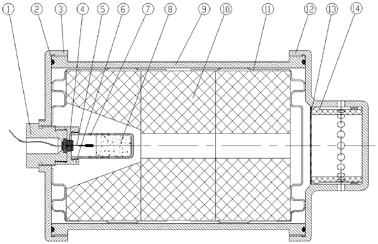
[0055] figure 1 It is a sectional view of a generator, showing an embodiment of the gas generator for an inflatable liferaft according to the present invention. As shown in the figure, the gas generator includes a generator housing 9, a generator upper cover 3 and a generator lower cover 12. The generator upper cover 3 is in the form of a cylinder, and a threaded hole is left in the middle for installation and ignition. device, the ignition device can also be connected with the generator upper cover 3 by welding. The generator lower cover 12 is cylindrical and has an exhaust hole on the peripheral side wall. The generator shell 9 is connected with the generator upper cover 3 and the generator lower cover 12 by thread or welding. The gas generator also includes an electric ignition type ignition device, which includes an igniter head 1, an ignition plug 4, an electronic igniter 5, a pressure cap 6, and an igniter housing 7 equipped with an igniting powder 8, and the gas genera...

Embodiment 2

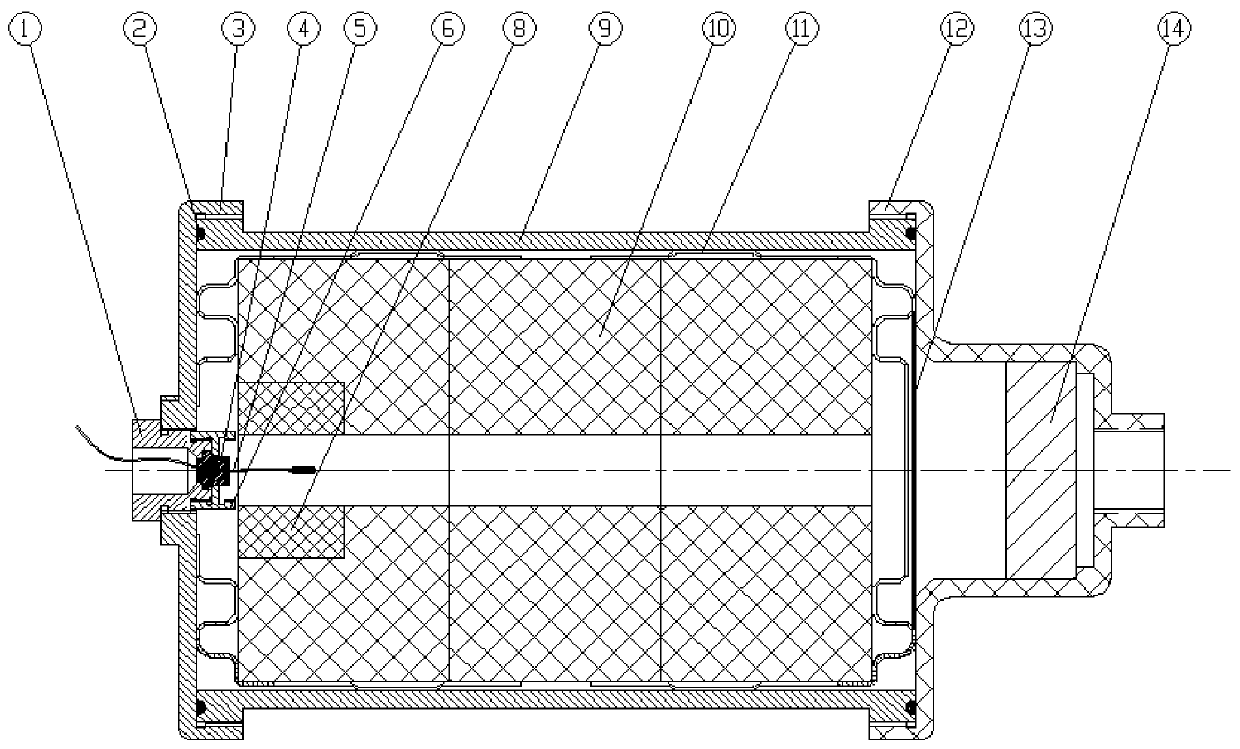
[0063] figure 2 An exemplary embodiment of a gas generator for an inflatable liferaft is shown, in which an ignition device, a filter cooling device and an exhaust device according to an embodiment of the present invention are used. The exhaust device is actually the lower cover 11 of the generator. The gas generated by the combustion of the gas generating agent 10 is discharged through the exhaust port at the bottom of the lower cover 12 of the generator, and the inside of the lower cover 12 of the generator needs to be made into a boss for placing cakes. Shape filter screen 14 (ie expanded metal).

[0064] The ignition device is composed of an igniter head 1, an ignition plug 4, an electronic igniter 5 and a pressure cap 6. The ignition wire of the electronic igniter 5 is passed through the ignition plug 4, and then the ignition plug 4 with the ignition wire is put on the pressure cap. 6, it is tightly connected with the igniter head 1 by threads. Due to the requirement t...


PUM

PropertyMeasurementUnit
Gapaaaaaaaaaa

Abstract

The invention relates to a gas generator for an inflatable life raft. The gas generator comprises a generator shell, a generator upper cover, a generator lower cover and a gas generating agent grain;the generator upper cover and the generator lower cover are fixedly arranged at two ends of the generator shell, and an inner cavity formed by the generator upper cover and the generator lower cover is used as a combustion chamber of the generator; and the gas generating agent grain is fixedly arranged in the combustion chamber through a positioning device. One of the generator upper cover and thegenerator lower cover is used for installing an ignition device, the other one is provided with a filtering and cooling device, and gas generated after the gas generating agent grain is combusted isdischarged after being filtered and cooled by the filtering and cooling device.

Description

technical field [0001] The invention relates to a gas generator for an inflatable liferaft. More specifically, it relates to a gas generator for an inflatable liferaft that uses a combination of single or multiple compressed grains, one end is ignited and the other end is exhausted. This gas generator is used to inflate different sizes and types of inflatable liferafts. Background technique [0002] The inflatable life raft is stored on the ship for emergency rescue when the ship is about to sink due to various reasons. Life rafts are generally bonded with adhesive tape. It has the characteristics of low cost, small footprint, light weight, rapid release, safety and reliability. [0003] An inflatable liferaft generally consists of a ceiling, an upper air chamber, a lower air chamber, a raft bottom, and an inflatable device. It has been proved in a series of marine accidents that the inflatable life raft can effectively save people's lives. The inflation devices of infl...

Claims


Application Information

Patent Timeline
IPC IPC(8): B63C9/04B63C9/18
CPCB63C9/04B63C9/18B63C2009/042
Inventor 王秋雨王亚王晨薛海龙胡小佳朱李宁习亮刘柳罗运强姚俊
Owner HUBEI HANGPENG CHEM POWER TECH
Why Eureka
Try Eureka