Turbo compressor and refrigerator using same

A turbo compressor and impeller technology, applied in the fields of turbo compressors and refrigerators, can solve the problems such as the increase of the vibration force of the motor rotor and the decrease of the self-excited vibration speed of the rotating shaft, so as to suppress the vibration, simplify the oil supply path, prevent the Effects of Electrocorrosion

Pending Publication Date: 2019-10-01
JCBE日本合同会社
View PDF9 Cites 0 Cited by
  • Summary
  • Abstract
  • Description
  • Claims
  • Application Information

AI Technical Summary

Problems solved by technology

[0017] However, when the motor is supported by a cantilever, the vibrating force of the motor rotor increases, and the rotational speed at which the rotating shaft generates self-excited vibration decreases.

Method used


Image

  • Turbo compressor and refrigerator using same
  • Turbo compressor and refrigerator using same
  • Turbo compressor and refrigerator using same

Examples


Embodiment approach 1

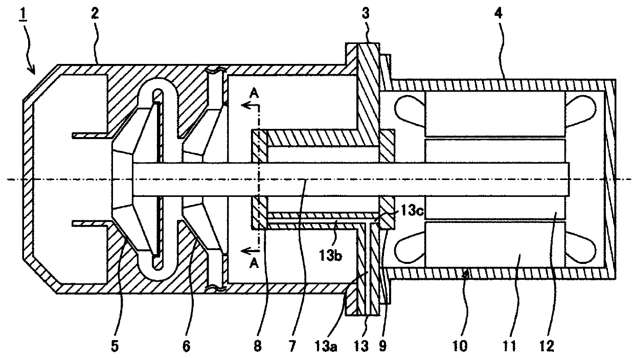
[0034] The present invention relates to a gearless turbo compressor which is a motor-direct type turbo compressor and a refrigerator using the turbo compressor. Here, the rotating shaft of the gearless turbo compressor is arranged in a substantially horizontal direction inside the casing, and is supported by a passive pressure sliding bearing.

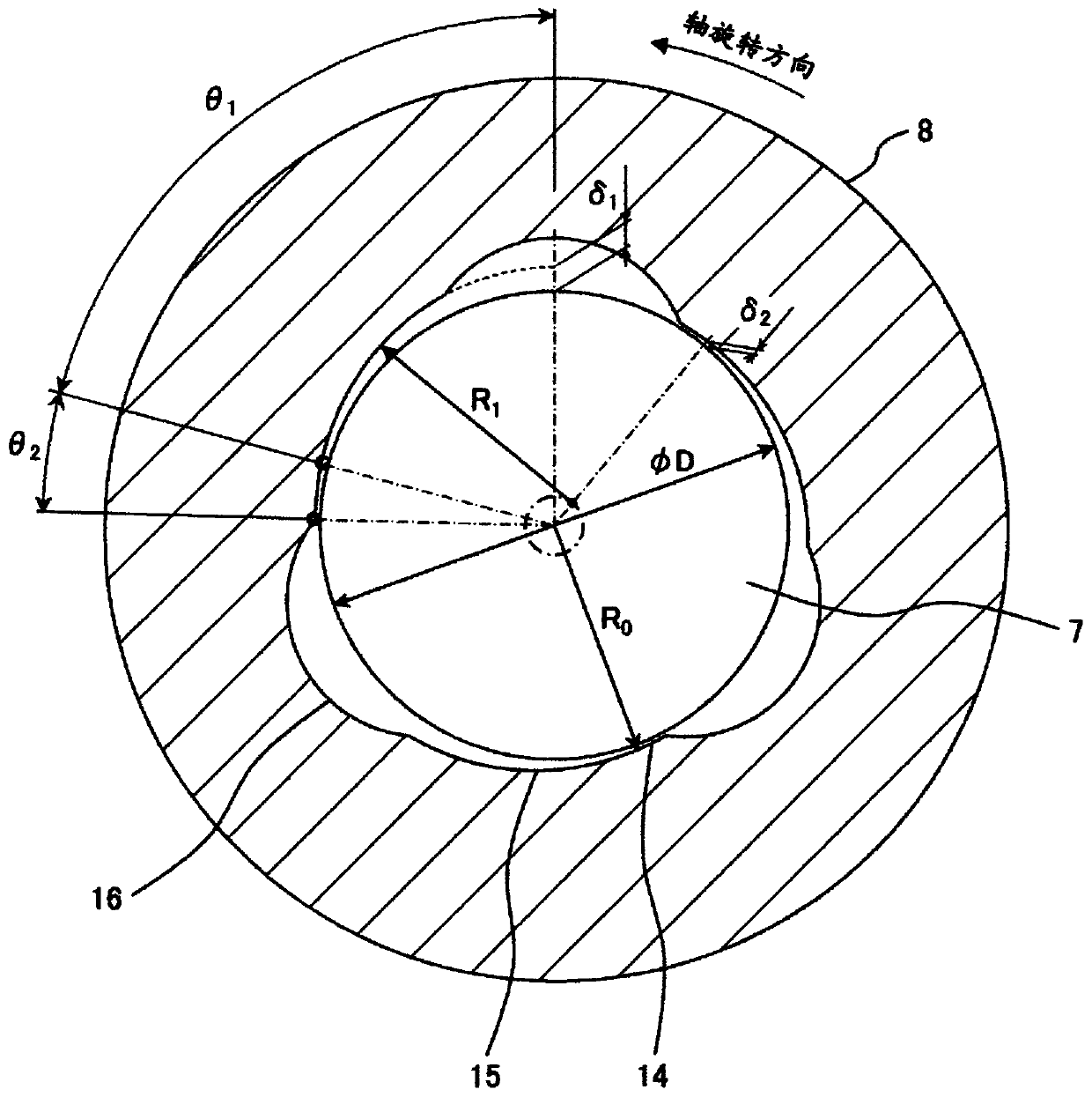
[0035] Here, the "approximately horizontal direction" includes directions inclined by about 10 degrees with respect to the positive horizontal direction perpendicular to the direction of gravity. This is the reason for considering the installation environment when the turbo compressor is installed. Of course, such a small angle of inclination relative to the horizontal direction is better, preferably less than 5 degrees, more preferably less than 3 degrees. Regardless of the angle, the vibration of the rotating shaft can be suppressed by using the dynamic pressure sliding bearing (multi-arc sliding bearing) of the present invention. ...

Embodiment approach 2

[0067] Figure 6 It is a schematic sectional view showing the overall structure of a turbo compressor according to another embodiment of the present invention.

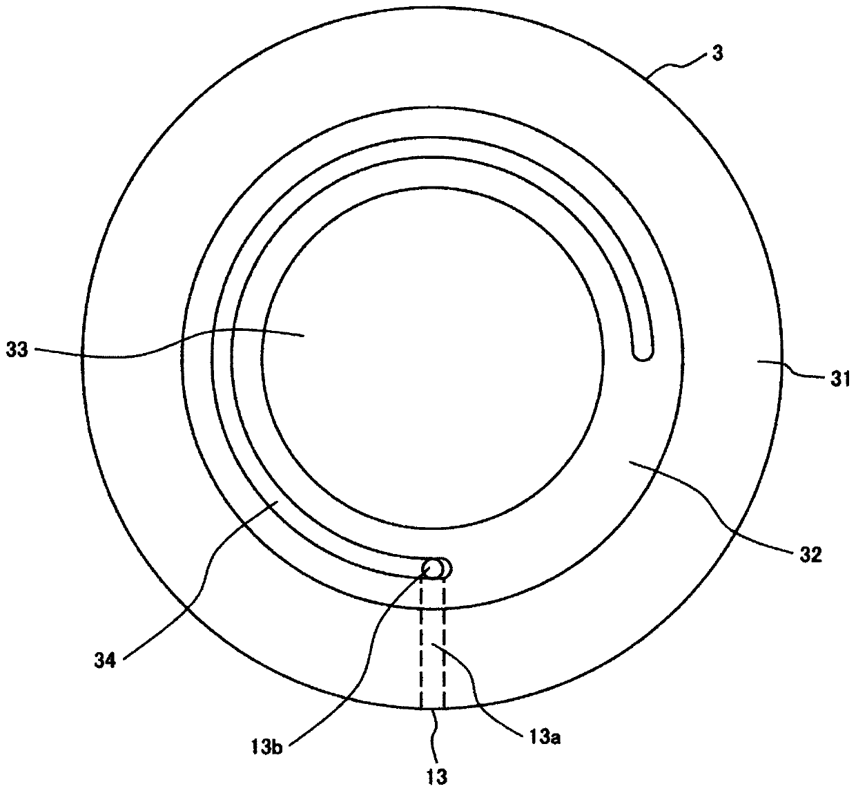
[0068] In this figure with figure 1 A different aspect is that the bearing portion is constituted by the multi-arc sliding bearings 68 and 69 having small-diameter portions. The small-diameter portion is inserted into the bearing housing 3 . The bearing housing 3 has oil supply passages 13d and 13e connected to the oil supply passage 13b. The oil supply path 13d of the bearing housing 3 supplies lubricating oil to the small-diameter portion of the multi-arc sliding bearing 68 , and the oil supply path 13e of the bearing housing 3 supplies lubricating oil to the small-diameter portion of the multi-arc sliding bearing 69 .

[0069] Figure 7 is going Figure 6 The perspective view of the disassembled multi-arc sliding bearing 68 viewed from the side of the bearing housing 3 .

[0070] exist Figure 7 Among them, ...

Embodiment approach 3

[0074] Embodiments 1 and 2 have two bearings, both of which are multi-arc sliding bearings, but are not limited thereto, and one may be a perfect circular sliding bearing. exist Figure 9 An example of a perfect circular sliding bearing is shown in . The perfect circular plain bearing is set to the figure 1 Any one of the two bearings represented by symbols 8 and 9, the other is a multi-arc sliding bearing (for example, a three-arc bearing).

[0075] When at least one of them is a multi-arc sliding bearing, the effect of suppressing the wobbling of the rotary shaft can be obtained.

[0076] In addition, the multi-arc sliding bearing can accurately form the pressure distribution of the lubricating oil when the rotating shaft rotates forward. In addition, when the compressor suddenly stops, the rotating shaft is temporarily reversed due to the reverse flow of the refrigerant gas, and the above-mentioned effects of the multi-arc sliding bearing may not be sufficiently obtained...


PUM


Abstract

The present invention provides a turbo compressor that prevents electric corrosion caused by a circulating current of a motor in a turbo compressor having a direct connection structure of a motor andsupporting a rotor of the motor with a sliding bearing, does not require an insulating structure, simplifies an oil supply path, and suppresses rotation of a rotating shaft, and allows high-speed rotation. The turbo compressor includes a motor including a stator and a rotor, an impeller, a rotating shaft that directly connects the rotor and the impeller, at least two bearings that support the rotating shaft by lubricating oil disposed between the rotor and the impeller, and a housing that accommodates the above parts. The rotating shaft is disposed in a substantially horizontal direction, therotor is supported by the rotating shaft cantilever, and at least one of the at least two bearings is a multi-arc sliding bearing.

Description

technical field [0001] The present invention relates to a turbo compressor and a refrigerator using the turbo compressor. Background technique [0002] The turbo compressor has an electric motor, an impeller, and a rotating shaft that transmits the power of the electric motor to the impeller. Here, when the rotating shaft is divided into two separate parts, that is, the motor rotating shaft and the impeller rotating shaft, it is common to provide a speed-up gear that connects these rotating shafts, and each rotating shaft is rotatably supported by bearings. . In this case, the power of the motor is transmitted to the impeller rotation shaft through the speed increasing gear. [0003] On the other hand, there is also a gearless turbo compressor having a structure that does not use such a step-up gear. In the case of a gearless turbo compressor, the power of the electric motor is transmitted directly through a rotating axial impeller. By eliminating the gear loss in the st...

Claims


Application Information

Patent Timeline
Patent Type & Authority Applications(China)
IPC IPC(8): F04D25/06F04D17/10F04D29/056F04D29/063F04D29/42
CPCF04D17/10F04D25/06F04D29/056F04D29/063F04D29/426
Inventor 佐藤充岩崎智彦岩田敦志
Owner JCBE日本合同会社
Why Eureka
Try Eureka