A Method for Measuring Wall Shear Stress

A measurement method and technology of shear stress, which are applied in measurement devices, measurement of fluid pressure, and hydrodynamic tests, etc., can solve the problems of inability to measure the near-wall area at the same time, limited application range, and difficulty in obtaining dynamic information of wall shear stress, etc. Suppresses the formation of flow structures with large shear stress, promotes the formation of flow structures with small shear stress, and is beneficial to drag reduction and control

Active Publication Date: 2020-05-01
TSINGHUA UNIV
View PDF7 Cites 0 Cited by
  • Summary
  • Abstract
  • Description
  • Claims
  • Application Information

AI Technical Summary

Problems solved by technology

[0003] Traditional wall shear stress measurement methods include direct measurement methods and indirect measurement methods. Direct measurement methods include surface oil film method, floating balance method, surface hot film method, etc. Such measurement methods generally have large calibration errors, difficult installation, and poor frequency response. Low-level problems, it is difficult to meet the requirements of accurate measurement of fluid wall shear stress, and can only roughly measure the distribution of shear stress; indirect measurement methods mainly rely on pitot tubes, hot wire anemometer (HWA), laser Doppler velocimeter (LDV) instrument measurement Velocity boundary layer, according to the distribution characteristics of the boundary layer (such as linear region, logarithmic region, etc.), the wall shear stress can be obtained indirectly, but this kind of measurement method is limited in scope, for example, Pitot tube is not applicable in supersonic flow, because There is an isolated shock wave at the head of the pitot tube, and the total pressure hole feels the total pressure after the wave, and the static pressure of the incoming flow is difficult to measure accurately; and the existing hot wire anemometer (HWA) cannot measure the velocity at different heights near the wall area at the same time , it is necessary to measure the velocity at different heights multiple times, and then calculate the wall shear stress in the near wall area; while the laser Doppler velocimeter (LDV) needs to have a certain transparency for the measured fluid, when measuring the velocity of pure water or air When the flow rate is high, it is necessary to artificially add an appropriate amount of particles as the scattering center. When the flow rate is high, it is required to increase the laser output power. Due to the high frequency of the signal, it is difficult to process the signal. The limitations are relatively large, and it is also difficult to obtain the dynamics of the wall shear stress. information
[0004] For example, Chinese patent CN108387483A discloses a method for measuring wall shear stress, which discloses the use of sensors to measure wall shear stress. The sensor is composed of two pieces of nickel foil and a layer of polyimide film. Temperature, one of the nickel foils is in direct contact with the fluid in the flow field, and exchanges heat with the fluid, as a sensitive element; the other nickel foil is installed at the corresponding position on the other side of the polyimide film, as the substrate of the sensitive element, using When the sensor measures the wall shear stress, the sensor is pasted on the wall by an adhesive, and the current passing through the nickel foil and the voltage across the nickel foil are used to calculate the heating power of the element, thereby calculating the shear stress at the sensor position , although this measurement method does not need to calibrate the sensor, there are still some problems in this measurement method. During the measurement, the sensor needs to be attached to the wall with an adhesive before measurement. If the measurement needs to be performed on the wall at another position When measuring shear stress, the sensor must be torn off from the wall first and then pasted to the position to be measured for measurement. The measurement process is more complicated, and it is easy to cause damage to the sensor during the tear-off process, resulting in the failure of the measurement process.

Method used


Image

  • A Method for Measuring Wall Shear Stress
  • A Method for Measuring Wall Shear Stress
  • A Method for Measuring Wall Shear Stress

Examples


Embodiment 1

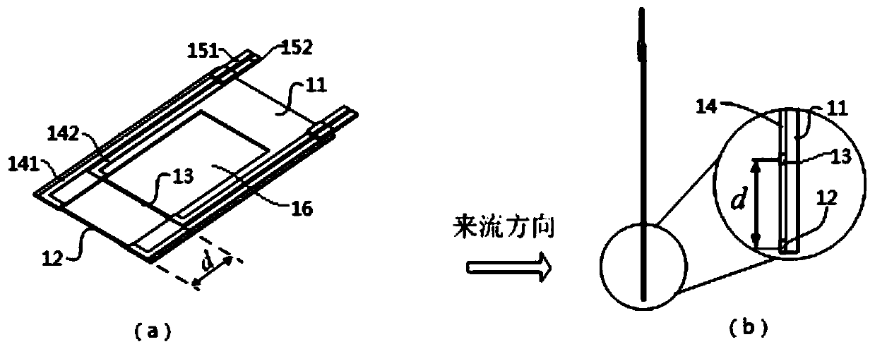
[0057] The parallel array hot wire probe of the present embodiment, such as image 3 As shown, it includes an insulating base 11, a first thermosensitive element 12 and a second thermosensitive element 13, wherein the insulating base 11 is in a substantially concave shape, and one end is the end near the wall (such as image 3 The left end shown in (a)) is provided with ventilation groove 16, and the first thermosensitive element 12 and the second thermosensitive element 13 are collinearly arranged at intervals, and the distance is d, and the first thermosensitive element 12 and the second thermosensitive element Both ends of 13 are fixed on the insulating base 11 and both straddle the ventilation groove 16; the first thermosensitive element 12 and the second thermosensitive element 13 are all platinum wires, thermocouples or other thermistors, which are not specifically limited The two ends of the first thermal element 12 are respectively connected with the first copper-clad ...

Embodiment 2

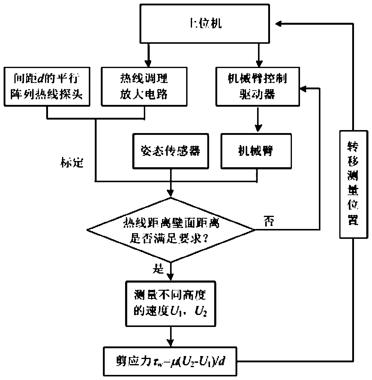
[0060] The wall shear stress measuring method of the present embodiment, such as Figure 1 to Figure 8 shown, including the following steps:

[0061] S1: Turn on the host computer 6, and set measurement tasks on the host computer 6;

[0062] The measuring task of upper computer 6 comprises position distribution and sampling frequency of points to be measured, and the sampling frequency of the hot-wire velocimeter of the present invention is up to 50KHz, and the higher the sampling frequency, the larger the data point value of collection; the sampling frequency can be selected according to demand, For example, a frequency of 1 KHz is adopted.

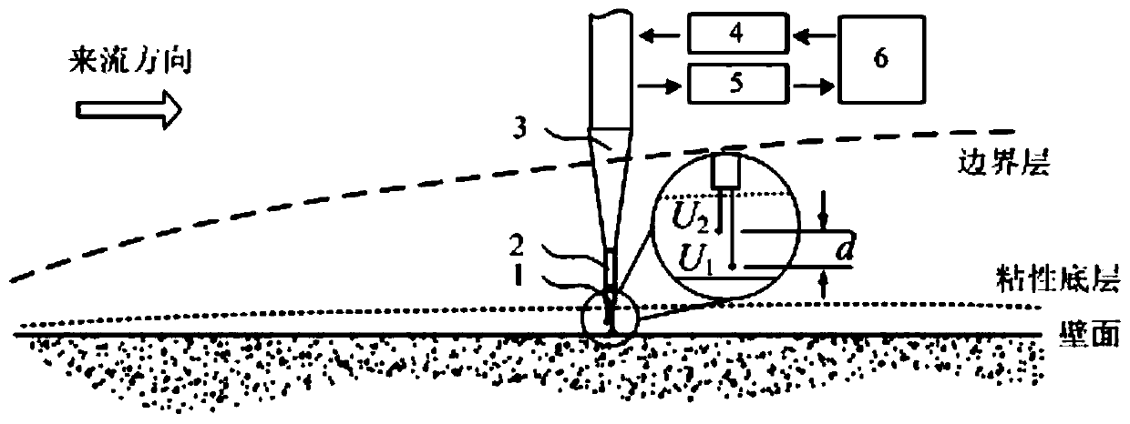
[0063] S2: Prepare the test piece, set the incoming flow velocity, and the direction of the incoming flow velocity is collinear with the plane where the wall surface of the test piece is located;

[0064] Such as figure 2 and image 3 As shown, the direction of the incoming flow is collinear with the plane where the wall surface of ...


PUM


Abstract

The invention belongs to the technical field of fluid measurement, and particularly relates to a parallel array hot line probe and a wall surface shearing force measurement method. According to a wallsurface shearing force measurement method, the speeds of two position points, far way from a wall surface at different heights, in a viscous bottom layer of a wall region, are simultaneously measuredin one time by the parallel array hot line probe, the fluctuating velocity is small, the additional shearing force generated by fluctuating velocity is also small, a viscous shearing force of the viscous bottom layer has a main guide effect, the speed in the viscous bottom layer and the wall surface distance are in linear distribution, and the product of slop (U2-U1) / d and a coefficient Mu of kinetic viscosity is a shearing force. The parallel array hot line probe is carried on a mechanical arm during measurement, a mechanical arm control driver is controlled to drive the mechanical arm to move and adjust by an upper computer, rapid moving of different positions of the wall surface can be achieved, and the measurement demand of the shearing force at different positions of the wall surfaceis solved very well.

Description

technical field [0001] The invention belongs to the technical field of fluid measurement, and in particular relates to a method for measuring wall shear stress. Background technique [0002] Wall shear stress is an important basic parameter for studying and judging the shape of flow field and the state of velocity boundary layer, but the measurement of wall shear stress has always been a difficult point in experimental fluid mechanics. With the continuous development of modern experimental fluid mechanics measurement technology, the new measurement technology of fluid wall shear stress has received more and more attention. [0003] Traditional wall shear stress measurement methods include direct measurement methods and indirect measurement methods. Direct measurement methods include surface oil film method, floating balance method, surface hot film method, etc. Such measurement methods generally have large calibration errors, difficult installation, and poor frequency respon...

Claims


Application Information

Patent Timeline
Patent Type & Authority Patents(China)
IPC IPC(8): G01L11/00G01L19/00G01M10/00
CPCG01L11/00G01L19/00G01M10/00
Inventor 徐胜金刘锦生傅奇星
Owner TSINGHUA UNIV
Why Eureka
Try Eureka