Feeding component and feeding robot adopting same

A technology of robots and components, applied in the direction of thin material handling, conveyor objects, winding strips, etc., can solve the problems of low degree of automation, high labor intensity, wrong loading of coil materials, etc., to reduce labor intensity and improve automation level , Improve the effect of running stability

Pending Publication Date: 2019-10-08
HUANGSHAN FUTIAN MACHINERY CO LTD
View PDF0 Cites 5 Cited by
  • Summary
  • Abstract
  • Description
  • Claims
  • Application Information

AI Technical Summary

Problems solved by technology

[0004] Another object of the present invention is to provide a special coil handling robot for disposable sanitary product production equipment, which combines AGV technology with special feeding tools to solve the problem of low automation, high labor intensity, and problems in traditional feeding methods. It is prone to the problem of wrong and reverse loading of coil materials

Method used


Image

  • Feeding component and feeding robot adopting same
  • Feeding component and feeding robot adopting same
  • Feeding component and feeding robot adopting same

Examples


Embodiment 1

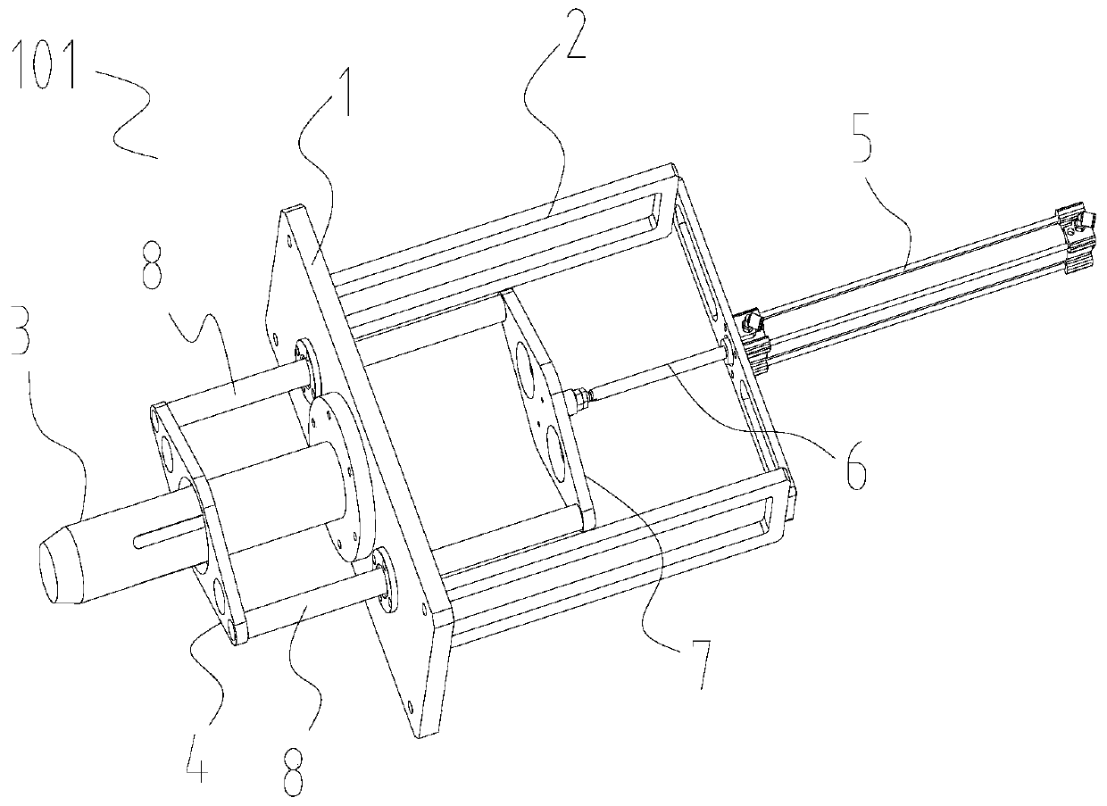
[0020] like figure 1 As shown, a feeding assembly 101 includes a base plate 1, a mounting frame 2 is fixed on one side of the base plate 1, and an inflatable shaft 3 for feeding is installed on the other side. A push plate 4 is provided, and the mounting frame 2 is provided with a cylinder 5 for driving the push plate 4 to move axially along the inflatable shaft 3 , and the piston rod of the cylinder 5 moves in a direction perpendicular to the base plate 1 during operation. The push plate 4 is sleeved on the inflatable shaft 3, and a connection part for transmitting the cylinder force is also provided between the cylinder 5 and the push plate 4. The connection part has an output shaft 6 connected with the cylinder 5, and a connection part connected with the output shaft. The connecting plate 7 and the guide rod 8 passing through the base plate 1 and connecting the connecting plate 7 and the push plate 4 .

[0021] In addition, there are two guide rods 8 arranged symmetrically...

Embodiment 2

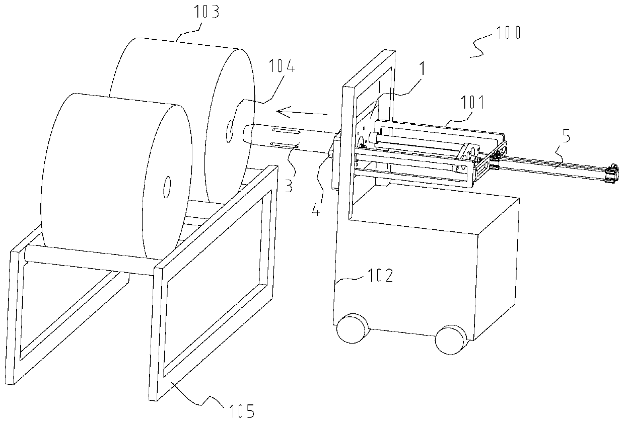
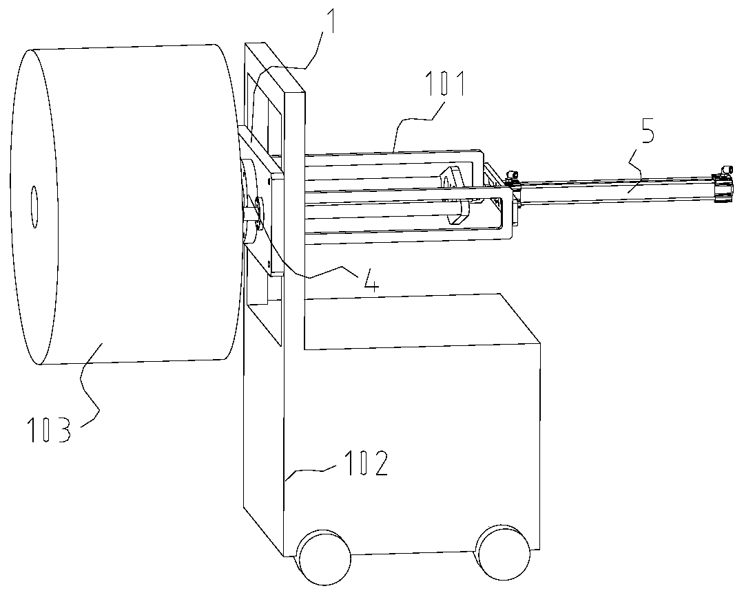
[0024] like Figures 2 to 4 As shown, an automatic feeding robot 100 is used to transport the coiled material 103 with the central hole 104 from the material rack 105 to the unwinding position 106. When the coiled material 103 is placed on the material rack 105, the central hole 104 The axis is parallel to the ground direction. Typically, the size of the central hole 104 is 70-80mm.

[0025] The above-mentioned automatic loading robot 100 includes: an automatic guided trolley 102 , a loading assembly 101 as described in Embodiment 1, and a compressed gas storage and control assembly for driving the inflatable shaft 3 and the cylinder 5 . The automatic guided vehicle 102 adopts magnetic navigation or laser navigation.

[0026] The automatic guided vehicle 102 can move along a predetermined trajectory according to instructions. The substrate 1 of the feeding assembly 101 is mounted on the automatic guided vehicle 102 and can move up and down in a direction perpendicular to the...


PUM


Abstract

The invention discloses a feeding component and a feeding robot adopting the same. The feeding component comprises a substrate, wherein a mounting frame is fixedly arranged on one side of the substrate; an air expansion shaft for feeding is arranged on the other side of the substrate; a push plate is also arranged at the axial peripheral part of the air expansion shaft; an air cylinder is arrangedon the mounting frame; during work, a piston rod of the air cylinder moves along the direction perpendicular to the substrate; the push plate is arranged on the air expansion shaft in a sleeving manner; and a connecting component is also arranged between the air cylinder and the push plate. The feeding robot is used for handling coil stock with a center hole from a rack to the unreeling positionand is provided with an automatic guided vehicle and a feeding component. The feeding robot disclosed by the invention can realize automatic taking, handling and feeding action of the coil stock by combined application of the automatic guided vehicle with the feeding component, so that labor intensity of workers is greatly reduced, and automatic level of equipment is improved; and meanwhile, misplaced and reverse loading of the coil stock in the manual handling and feeding process can be reduced and the operation stability of the equipment is improved.

Description

technical field [0001] The invention relates to the field of manufacturing disposable sanitary products, in particular to a feeding assembly and a feeding robot using the assembly. Background technique [0002] The raw materials used in the existing disposable sanitary products production line (including non-woven fabrics, toilet paper, PE film, dust-free paper, composite film, etc.) processing, and finally form products such as diapers and sanitary napkins. When the production speed of the production line is fast, the consumption of raw materials will be accelerated. At this time, the usual practice is to manually transport another coil to the designated position for material replacement. It can be seen that the traditional method has the disadvantages of high work intensity and low degree of automation. Problem, sometimes when the staff is handling and loading the material, there will be problems such as loading the coil material wrongly or reversely. Contents of the in...

Claims


Application Information

Patent Timeline
Patent Type & Authority Applications(China)
IPC IPC(8): B65G47/74B65H19/12
CPCB65G47/74B65H19/12B65H19/123
Inventor 龚志龙李大柱
Owner HUANGSHAN FUTIAN MACHINERY CO LTD
Why Eureka
Try Eureka