Protective covers for blast furnace cooling plate assemblies

A technology of cooling plate and protective cover, applied in the direction of cooling device, etc., can solve the problems of large temperature difference inside and outside the furnace shell 10, the degree of welding seam cracking becomes larger, and the welding seam cracking, etc., to enhance the cooling effect, easy to adjust, and slow down the welding seam. cracking effect

Active Publication Date: 2021-11-16
BAOSHAN IRON & STEEL CO LTD
View PDF2 Cites 0 Cited by
  • Summary
  • Abstract
  • Description
  • Claims
  • Application Information

AI Technical Summary

Problems solved by technology

[0004] The sleeve 30 is directly welded to the furnace shell 10. Due to the high temperature in the furnace, the temperature difference between the inside and outside of the furnace shell 10 is relatively large, and the resulting stress on the furnace shell 10 causes the weld between the sleeve 30 and the furnace shell 10 to often crack, resulting in Pressure fire and red spatter fly out. The existing treatment method is to use external water spray to cool the weld seam. However, in the case of sudden cooling, the furnace shell shrinks slightly, and the cracking degree of the weld seam becomes larger instead. A large amount of rebounding water and high-temperature steam are generated, a large amount of gas leaks mixed with red splashes, and is accompanied by a sharp sound of air leakage, and the online production cannot be repaired at close range, and the blast furnace can only be treated with wind reduction or shutdown, which affects normal production

Method used


Image

  • Protective covers for blast furnace cooling plate assemblies
  • Protective covers for blast furnace cooling plate assemblies
  • Protective covers for blast furnace cooling plate assemblies

Examples


Embodiment Construction

[0021] Below, the structure and working principle of the present invention will be further described in conjunction with the accompanying drawings.

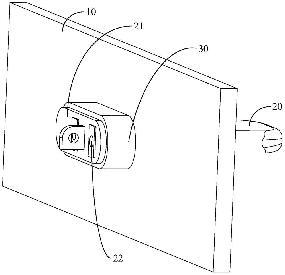
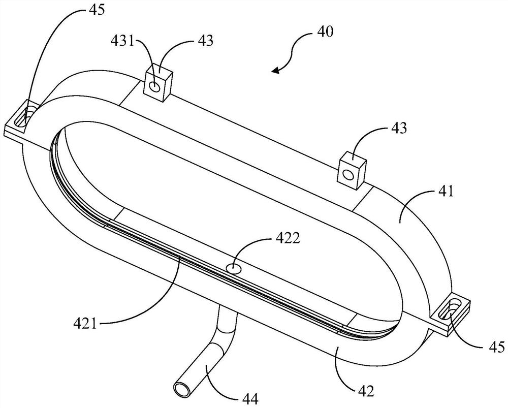
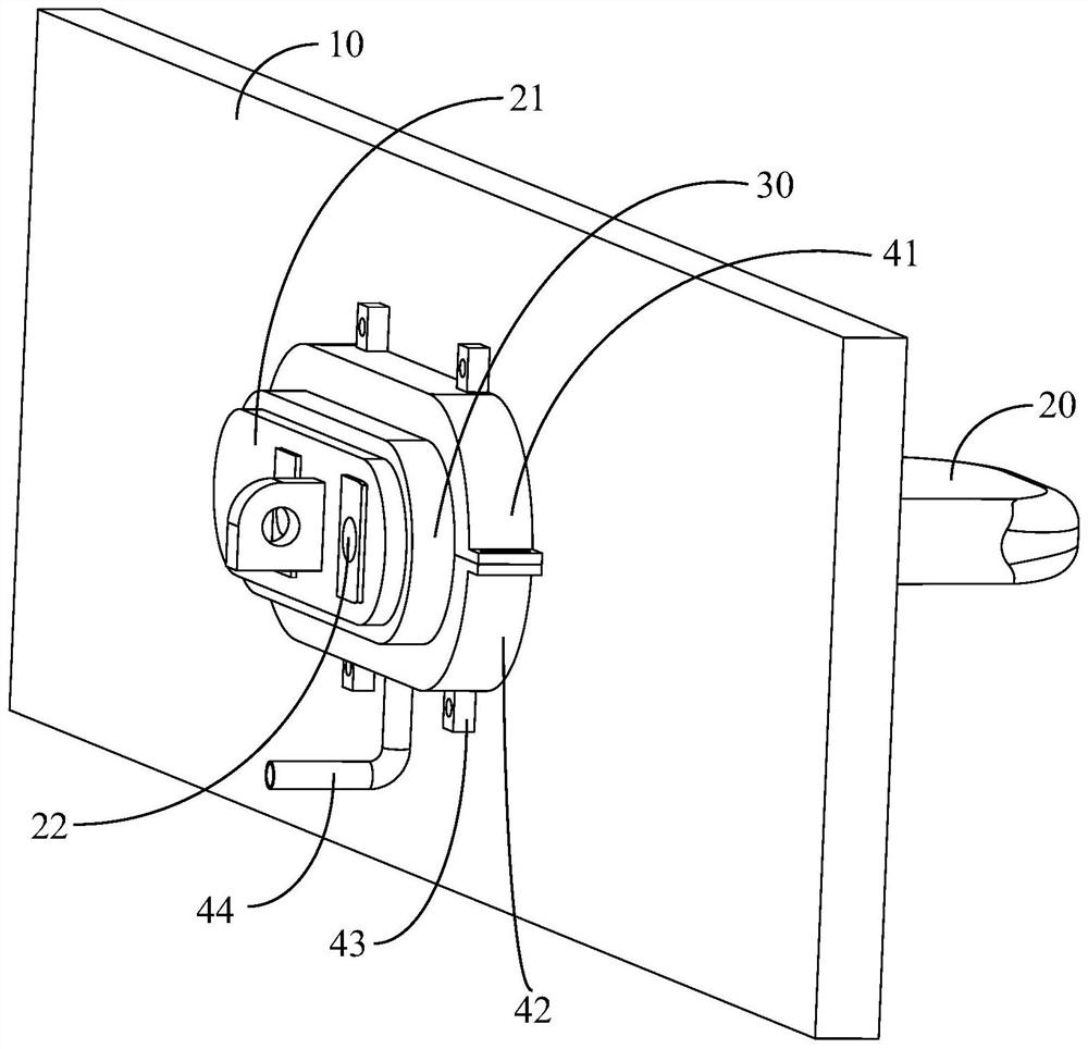
[0022] see figure 2 and combine image 3 , the protection cover 40 used for the blast furnace cooling plate assembly of the present invention is sleeved on the outside of the casing 30 and installed on the furnace shell 10 , wherein the gap fit between the protection cover 40 and the casing 30 . Once the weld seam between the sleeve pipe 30 and the furnace shell 10 cracks, pressure flames and red spatters are ejected, the protective cover 40 can suppress the pressure flames and prevent the red spatters from flying out. Since the plurality of cooling plates 20 on the furnace shell 10 are connected by piping, in order to facilitate the disassembly of the protective cover 40, the protective cover 40 can be made into a split structure. As a method, the protective cover 40 includes an upper cover 41 and a lower cover. 42. The upper...


PUM


Abstract

The invention discloses a protective cover for a blast furnace cooling plate assembly. The cooling plate assembly includes a cooling plate and a casing welded to the blast furnace shell. The cooling plate is fixed to the casing and passes through the casing. The casing extends into the furnace body of the blast furnace, the protective cover is sleeved on the outside of the casing and installed on the furnace shell, and the protective cover and the casing are in clearance fit, so The protective cover includes an upper cover and a lower cover, the upper cover and the lower cover are detachably connected, and the lower cover is provided with a water injection port, and the water injection port is connected with a connection between the casing and the furnace shell. The water injection pipe for the weld injection. Adopting the protection cover for the blast furnace cooling plate assembly of the present invention can effectively prevent or slow down the cracking of the weld seam between the sleeve pipe and the furnace shell, and can also suppress pressure fire and prevent red splashes from flying out.

Description

technical field [0001] The invention relates to the field of blast furnace body cooling equipment, in particular to a protective cover for a blast furnace cooling plate assembly. Background technique [0002] The blast furnace cooling plate assembly is an important equipment of the blast furnace. During the production process of the blast furnace, the high temperature caused by a large amount of heat generated by the physical and chemical reactions of the internal charge is borne by the refractory materials built in the blast furnace shell. The blast furnace cooling plate assembly can The refractory material is cooled, thereby prolonging the service life of the refractory material and ensuring the stable production of the blast furnace. [0003] There are two structural forms of blast furnace cooling plate components: flange connection type and welding type. figure 1 It is a structural schematic diagram of a welded blast furnace cooling plate assembly, wherein only a part o...

Claims


Application Information

Patent Timeline
Patent Type & Authority Patents(China)
IPC IPC(8): C21B7/10
CPCC21B7/10
Inventor 费明朱郁文许贇秋沈晓勇居勤章黄琦
Owner BAOSHAN IRON & STEEL CO LTD
Why Eureka
Try Eureka