
A steel truss arch support and its construction method

A technology of steel truss and installation part, which is applied in the field of steel truss arch support and its construction, which can solve the problems of difficulty in ensuring the stability of steel truss arch, increase of manpower and mechanical equipment, and single support fixing method, so as to reduce the number of machinery and personnel The effect of consumption, reduction of construction period, and shortening of slippage time

Active Publication Date: 2021-05-25
广西天正钢结构有限公司
View PDF0 Cites 0 Cited by
  • Summary
  • Abstract
  • Description
  • Claims
  • Application Information

AI Technical Summary

Problems solved by technology

In the process of hoisting and sliding, the stability of the steel truss arch is difficult to guarantee, which is greatly affected by environmental factors and operating levels. A slight wind influence or operation error will cause position deviation or impact buffering of the steel truss arch; in addition, the sliding process The thrust in the middle is the moving foundation of the steel truss arch. The sliding resistance in the sliding process increases the required thrust and slows down the installation, especially for large truss arches. In addition, the process of first installing the truss arch and then installing the support The installation process is complicated, and the manpower and mechanical equipment are greatly increased. After the steel truss arch is in place, the support is fixed in a single way. Before the support is completely installed, the steel truss must be kept in a continuous stable state, which is time-consuming and difficult.

Method used


Image

  • A steel truss arch support and its construction method
  • A steel truss arch support and its construction method

Examples


Embodiment Construction

[0024] Now, the structure and principle of the present invention will be fully described in conjunction with specific embodiments, so that those skilled in the art can fully understand and implement it.

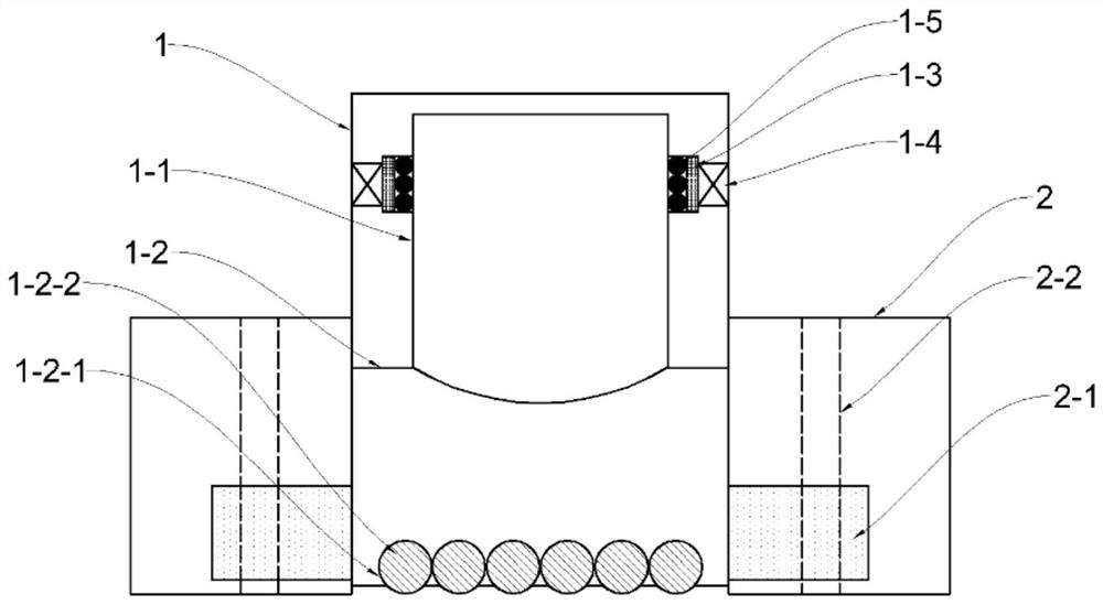
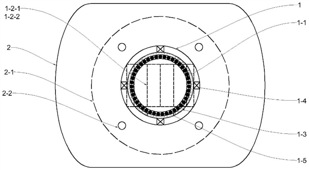
[0025] Such as Figure 1-Figure 2 As shown, a steel truss arch support according to the present invention includes a connecting part 1 and a mounting part 2; the connecting part 1 is cylindrical, and the mounting part 2 is fixedly sleeved on the outside of the connecting part 1; the connecting part 1 is provided with a connecting plate 1-1, and the connecting plate 1-1 is rotated and connected with a sliding plate 1-2, and the sliding plate 1-2 is fixedly connected with the connecting part 1, and the connecting plate 1-1 is columnar The periphery is sleeved on the inner side of the positioning steel ring 1-3 through the positioning ball 1-5 and the cage, and the outer side of the positioning steel ring 1-3 is fixedly connected with the inner wall of the connecting part 1 thro...


PUM


Abstract

The invention discloses a steel truss arch support, which belongs to the technical field of building construction and comprises a connection part and an installation part; the connection part is cylindrical, and the installation part is fixedly sleeved on the outside of the connection part; The connecting plate, the connecting plate is connected with a sliding plate under the rotation, and the sliding plate is fixedly connected with the connecting part, and the connecting plate is a columnar periphery which is sleeved on the inner side of the positioning steel ring through positioning balls and cages, and the positioning steel ring The outer side is fixedly connected with the inner wall of the connecting part through elastic parts. There are several columnar grooves on the lower surface of the sliding plate, and the needle balls are installed in the grooves. The columnar grooves are aligned with the sliding direction of the steel truss arch support. Vertical; the mounting part is flush with the bottom of the connecting part and the lower surface of the needle roller ball. The mounting part is symmetrically provided with several bolt holes penetrating up and down. connected. The arch support of the invention can simplify the installation process, and the installation effect is firm.

Description

technical field [0001] The invention relates to the technical field of building construction, in particular to a steel truss arch support and a construction method thereof. Background technique [0002] Steel trusses refer to trusses made of steel, roof structures such as crane girders, bridges, and hydraulic gates for industrial and civil buildings. Steel trusses are commonly used as the main load-bearing components. Various towers, such as mast towers, TV towers and transmission line towers, are commonly used as space steel trusses composed of three-sided, four-sided or multi-sided planar trusses. [0003] The steel truss arch construction in the prior art mostly draws the steel truss arch to the designated position by traction equipment on the basis of setting the sliding track, and then lifts the steel truss arch by hoisting equipment and installs the support to realize the installation of the steel truss arch . In the process of hoisting and sliding, the stability of ...

Claims


Application Information

Patent Timeline
Patent Type & Authority Patents(China)
IPC IPC(8): E04B1/36E04G21/16
CPCE04B1/36E04G21/16
Inventor 谢振宁
Owner 广西天正钢结构有限公司
Learn More