Angular contact ball bearing retainer

An angular contact ball bearing and cage technology, applied in the field of bearings, can solve the problem of uncertain collision positions between rolling elements and cage pockets, large contact friction between rolling elements and cages, and easy scratching of rolling elements in the cage pockets, etc. problems, to achieve the effect of improving operational stability, reducing scratches, and extending service time

Pending Publication Date: 2019-10-08
TIAN JI BEARING TECH ZHEJIANG CO LTD
View PDF0 Cites 0 Cited by
  • Summary
  • Abstract
  • Description
  • Claims
  • Application Information

AI Technical Summary

Problems solved by technology

[0005] 2. The contact friction between the rolling element and the cage is large, and the heat generation is large
[0006] 3. The edge of the cage pocket is easy to scratch the rolling element
[0007] 4. The position of the collision between the rolling element and the pocket of the cage is uncertain, which makes the operation of the cage unstable

Method used


Image

  • Angular contact ball bearing retainer
  • Angular contact ball bearing retainer
  • Angular contact ball bearing retainer

Examples


Embodiment Construction

[0043] The following are specific embodiments of the invention and in conjunction with the accompanying drawings, the technical solutions of the present invention are further described, but the present invention is not limited to these embodiments.

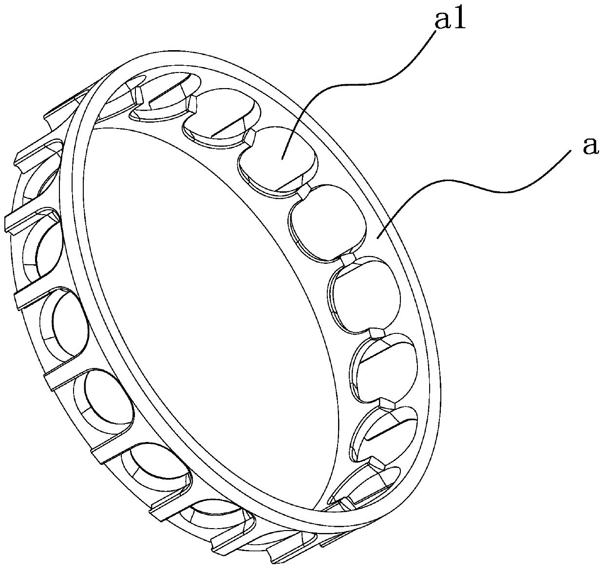
[0044] like figure 1 As shown, the cage of the angular contact ball bearing includes a cage body a, and a number of ball pockets a1 evenly distributed around the circumference are provided on the circumference of the cage body a, and the balls are placed in the ball pockets a1.

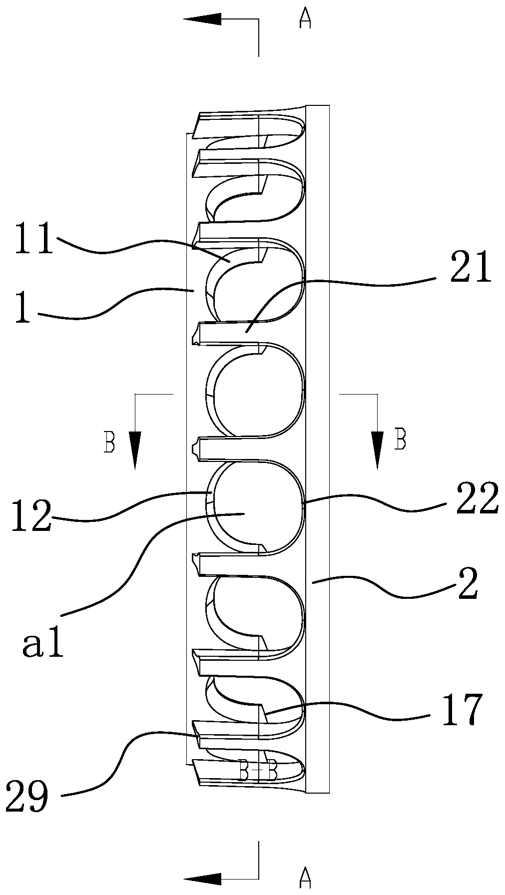
[0045] like figure 2 as shown,

[0046] The cage body a includes an inner ring 1 connected to one end with several inner lintels 11 evenly distributed around the circumference, and the inner lintels 11 and the inner ring 1 are connected as an integrated structure, that is, they are integrally formed by injection molding, which can improve the structure. strength.

[0047] Evenly distributed on the circumference can ensure the balance of gravity, and c...


PUM


Abstract

The invention discloses an angular contact ball bearing retainer. The angular contact ball bearing retainer comprises a retainer body, wherein the retainer body comprises an inner ring with one end connected with a plurality of inner side passing beams, a U-shaped inner conical pocket groove is formed by every two adjacent inner side passing beams and the inner ring, a middle arc-shaped contact convex surface I and an inner receding surface I which are sequentially connected from outside to inside are arranged in the middle of the groove wall of each inner conical pocket groove, inner arc-shaped contact convex surfaces which are arranged in the width direction of the groove wall of the corresponding inner conical pocket groove are arranged at the two ends of the groove wall of each inner conical pocket groove correspondingly, the retainer body further comprises an outer ring with one end connected with a plurality of outer side passing beams, a U-shaped outer conical pocket groove is formed by every two adjacent outer side passing beams and the outer ring, the outer side passing beams are fixed on the outer surfaces of the inner side passing beams in a one-to-one mode, the inner conical pocket grooves and the outer conical pocket grooves form ball pocket holes, a middle arc-shaped contact convex surface II and an inner receding surface II which are sequentially arranged from outside to inside are arranged in the middle of the groove wall of each outer conical pocket groove, and outer arc-shaped contact convex surfaces which are arranged in the width direction of the groovewall of the corresponding outer conical pocket groove are arranged at the two ends of the groove wall of each outer conical pocket groove correspondingly.

Description

technical field [0001] The invention belongs to the technical field of bearings, in particular to an angular contact ball bearing cage. Background technique [0002] There are mainly two methods of angular contact ball bearings for machine tool spindles: grease lubrication and oil-air lubrication. The two different lubrication methods have their own optimal cage structure design. [0003] The existing angular contact ball bearing cage has the following defects: [0004] 1. The structure of the grease lubricated bearing cage does not change. When it is used for oil-air lubrication, it is easy to generate noise due to the impact of oil and gas on the cage. [0005] 2. The contact friction between the rolling element and the cage is large, and the heat generation is large. [0006] 3. The edge of the cage pocket is easy to scratch the rolling element [0007] 4. The collision position between the rolling element and the pocket of the cage is uncertain, which makes the operat...

Claims


Application Information

Patent Timeline
Patent Type & Authority Applications(China)
IPC IPC(8): F16C33/41
CPCF16C33/416F16C19/163F16C33/3806F16C33/3837F16C33/3887F16C33/586F16C33/6662F16C2322/39
Inventor 徐从占邹鹏余礼韩婷
Owner TIAN JI BEARING TECH ZHEJIANG CO LTD
Why Eureka
Try Eureka