Harmonic transmission speed reducing mechanism

A technology of reduction mechanism and harmonic transmission, which is applied in the direction of transmission, transmission parts, mechanical equipment, etc., can solve the problems affecting the stability and accuracy of the harmonic reducer, the large size of the harmonic reducer, and the impact on the service life. Achieve the effects of improving the stability and accuracy of use, compacting the harmonic reducer, and reducing production costs

Inactive Publication Date: 2019-10-08
NINGBO ZHONGDA LEADER TRANSMISSION EQUIP
View PDF10 Cites 3 Cited by
  • Summary
  • Abstract
  • Description
  • Claims
  • Application Information

AI Technical Summary

Problems solved by technology

Although the harmonic reducer has the advantages of small size, large speed ratio, large torque and high transmission precision, most of the existing harmonic reducers have complex structures, and most of them use cup-shaped or hat-shaped flexible gears, the bottom of which is connected to the output end , its stress is mostly concentrated at the bottom, often due to excessive stress concentration and deformation, which affects its life. Because the existing harmonic reducer has many parts and the overall structure is not compact enough, it not only results in a larger volume of the harmonic reducer, but also increases the The raw materials are produced, and the output is not stable and accurate enough, which affects the stability and accuracy of the harmonic reducer.

Method used


Image

  • Harmonic transmission speed reducing mechanism
  • Harmonic transmission speed reducing mechanism
  • Harmonic transmission speed reducing mechanism

Examples


Embodiment Construction

[0020] In order to better illustrate and elaborate the content of the present invention, the following will be expanded and described in conjunction with schematic diagrams and implementation examples:

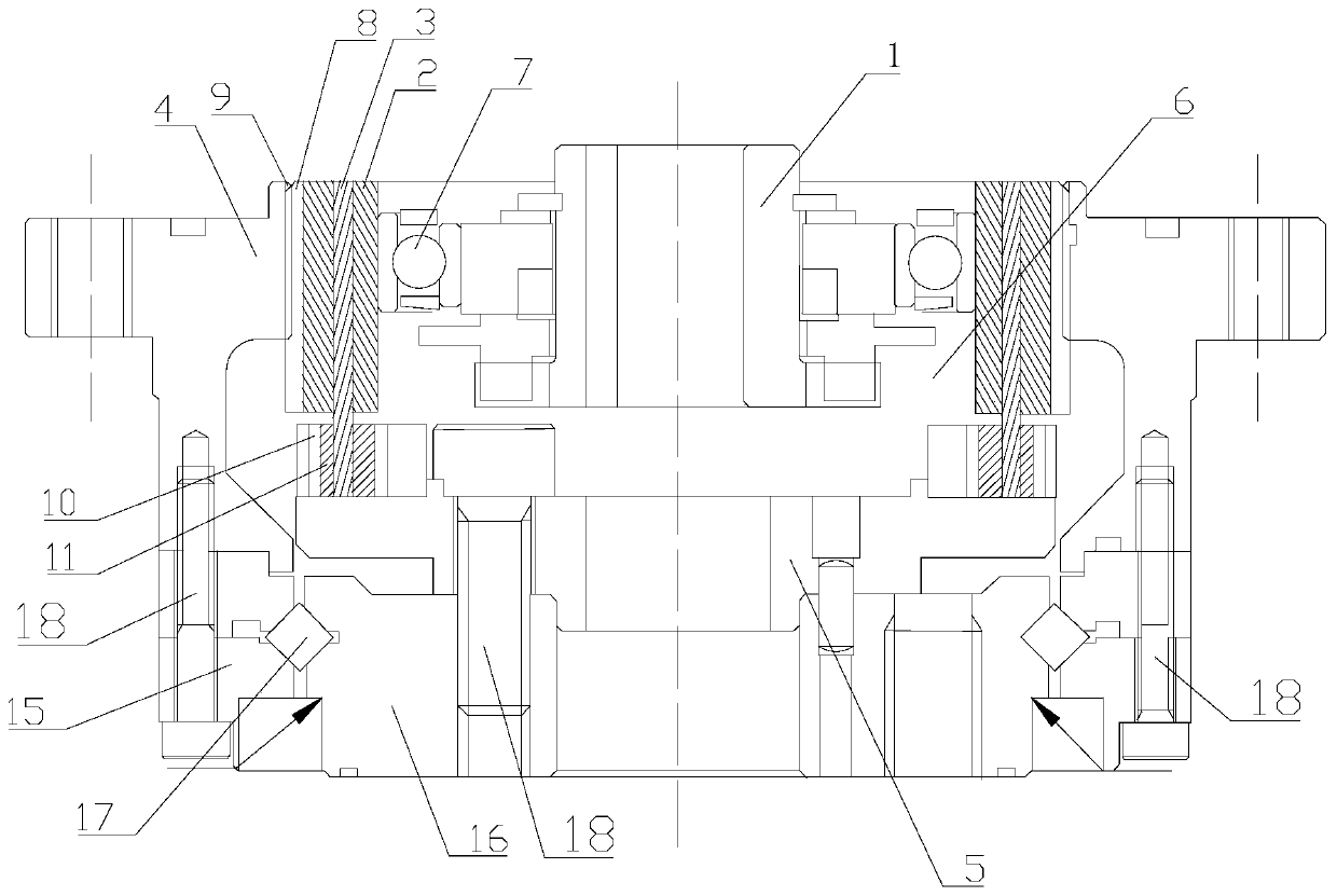
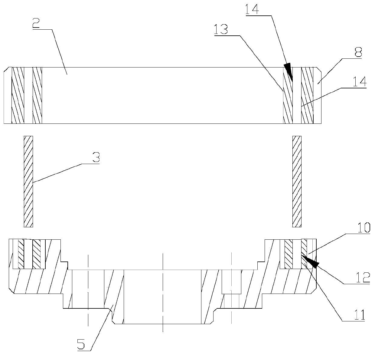
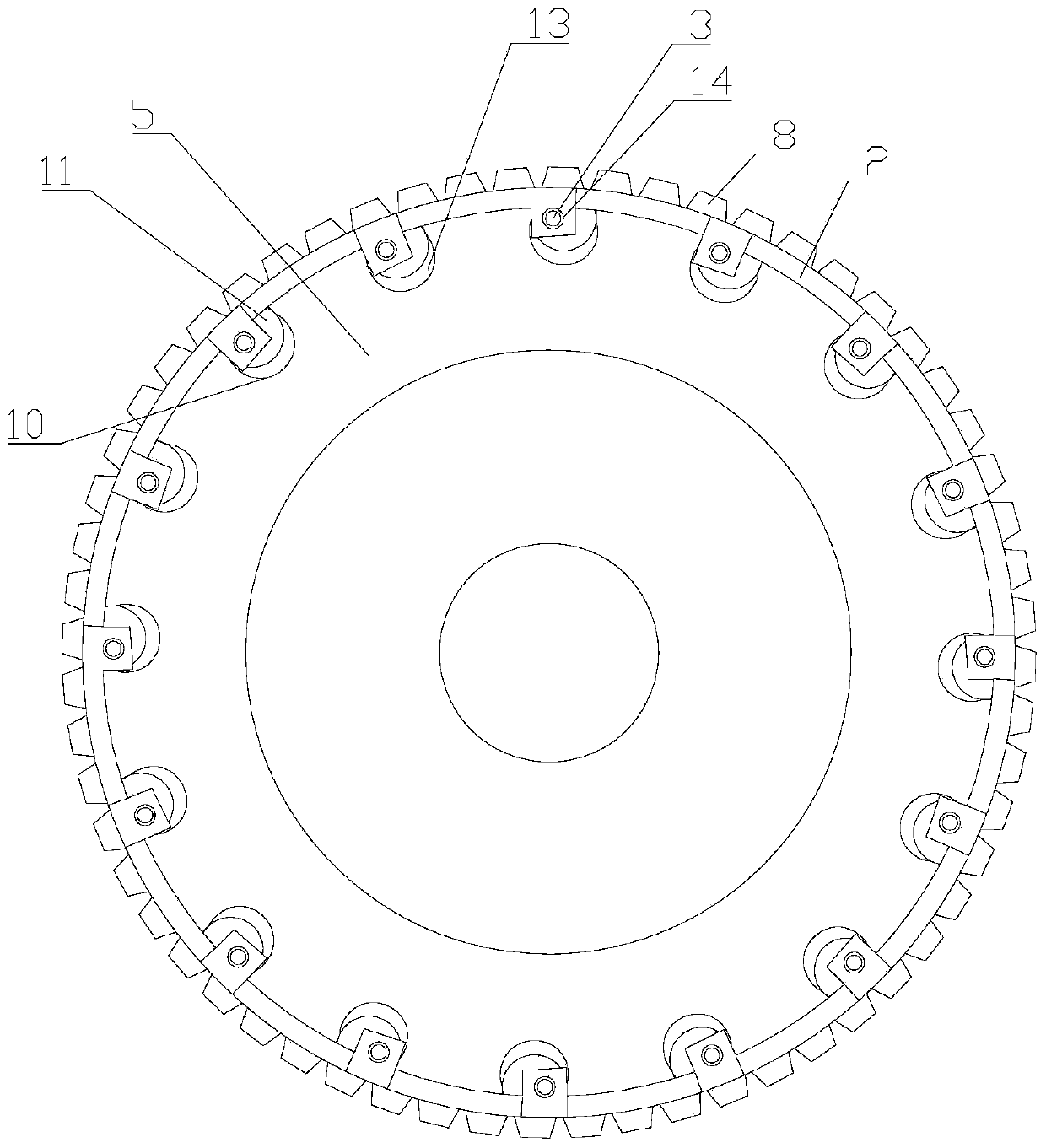
[0021] Depend on Figure 1-Figure 4 , the present invention provides a harmonic transmission reduction mechanism, including a wave generator, a flexible gear 2, a connecting pin 3, a rigid gear 4, a connecting ring 15, and an output plate 5; The accommodation space 6 for accommodating the wave generator 1 and the flexible gear 2, the top end surface of the connecting ring 15 and the bottom end of the rigid gear 4 are connected and fixed by bolts 18; the wave generator includes a cam 1 and a cam bearing 7 sleeved outside the cam 1, flexible The gear 2 is sleeved on the outside of the cam bearing 7, and the outer ring gear 8 of the flexible gear 2 is partially meshed with the inner ring gear 9 of the rigid gear 4.

[0022] Further, an adapter plate 16 is connected to the bottom...


PUM


Abstract

The invention discloses a harmonic transmission speed reducing mechanism. The mechanism comprises a wave generator, a flexible gear, a connecting pin, a rigid gear and an output plate, wherein an accommodating space capable of accommodating the wave generator and the flexible gear is arranged in the rigid gear in an up and down penetrating mode, the wave generator comprises a cam and a cam shaft bearing connected on the outer side of the cam in a sleeving mode, the flexible gear is connected to the outer side of the cam shaft bearing in a sleeving mode, an outer gear ring of the flexible gearis meshed with an inner gear ring of the rigid gear, a set of kidney-shaped grooves are uniformly distributed on the surface of the output plate along the axis, eccentric vertical wheels are arrangedin the kidney-shaped grooves, eccentric holes used for accommodating one end of the connecting pin to be inserted and fixed is formed in the top of the eccentric vertical wheels, connecting convex columns corresponding to the eccentric vertical wheels are distributed on the inner side wall of the flexible gear along the axis, the connecting convex columns are provided with connecting inserting holes used for accommodating the other end of the connecting pin to be inserted and fixed, and the connecting pin, the connecting convex columns and the eccentric vertical wheels are connected and matched with each other, so that the flexible gear and the output plate form a synchronous connection motion.

Description

technical field [0001] The invention relates to the field of reducers, in particular to a harmonic drive reduction mechanism. Background technique [0002] At present, with the progress of scientific and technological development, reducers are increasingly widely used in various fields. Among them, the harmonic reducer is a new type of reducer developed by using the principle of planetary gear transmission. It adopts the principle of harmonic gear transmission and passes through the wave generator ( Cam) is equipped with a flexible bearing so that the flexible gear produces controllable elastic deformation, and meshes with the rigid gear to transmit motion and power. The gear transmission forces the cross section of the flexible gear to change from the original circle to an ellipse, and its long axis is two The teeth near the end of the short shaft are completely meshed with the teeth of the rigid wheel, while the teeth near both ends of the short shaft are completely diseng...

Claims


Application Information

Patent Timeline
Patent Type & Authority Applications(China)
IPC IPC(8): F16H49/00F16H57/023
CPCF16H49/001F16H57/023
Inventor 岑庭炯罗跃冲黄炳
Owner NINGBO ZHONGDA LEADER TRANSMISSION EQUIP
Why Eureka
Try Eureka