Gas appliance, gas valve and control method of gas valve

A gas and appliance technology, applied in the field of gas appliances, gas valves and their control, can solve the problems of unstable gas flow, affecting the combustion efficiency of the burner 10, unstable gas pressure, etc.

Inactive Publication Date: 2019-10-08
GRAND MATE
View PDF11 Cites 0 Cited by
  • Summary
  • Abstract
  • Description
  • Claims
  • Application Information

AI Technical Summary

Problems solved by technology

[0004] The existing gas appliance 1 must use the pressure regulator 14 to keep the gas pressure input from the gas source to the gas valve 12 stable. However, when the pressure of the gas source 16 is less than a certain pressure, the output from the pressure regulator 14 will be Unstable gas pressure
Since the gas valve 12 adjusts the gas flow rate by changing the opening of its valve port, if the gas pressure input into the gas valve 12 is unstable, the gas flow rate will be unstable, thereby affecting the combustion efficiency of the burner 10

Method used


Image

  • Gas appliance, gas valve and control method of gas valve
  • Gas appliance, gas valve and control method of gas valve
  • Gas appliance, gas valve and control method of gas valve

Examples


Embodiment Construction

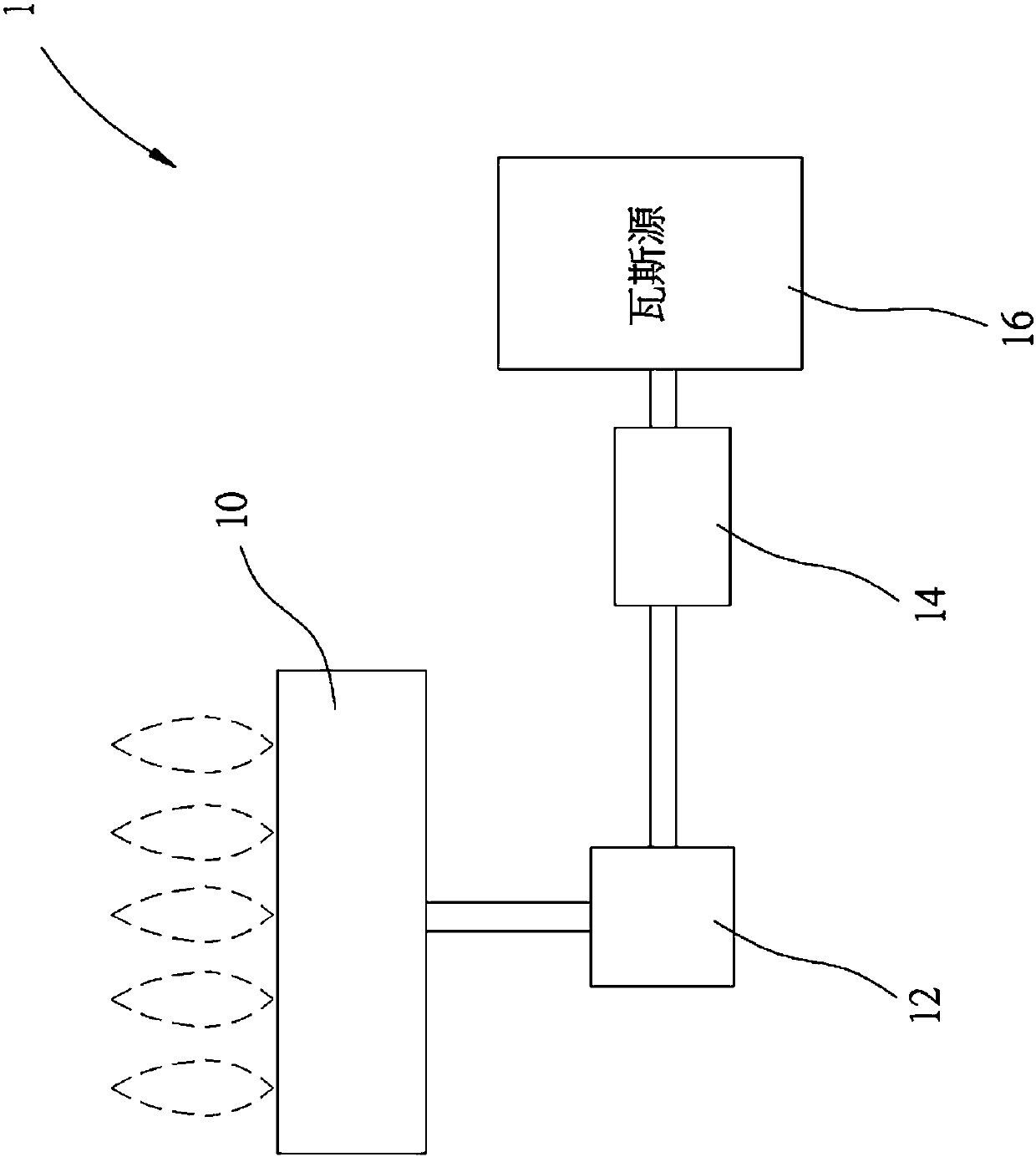
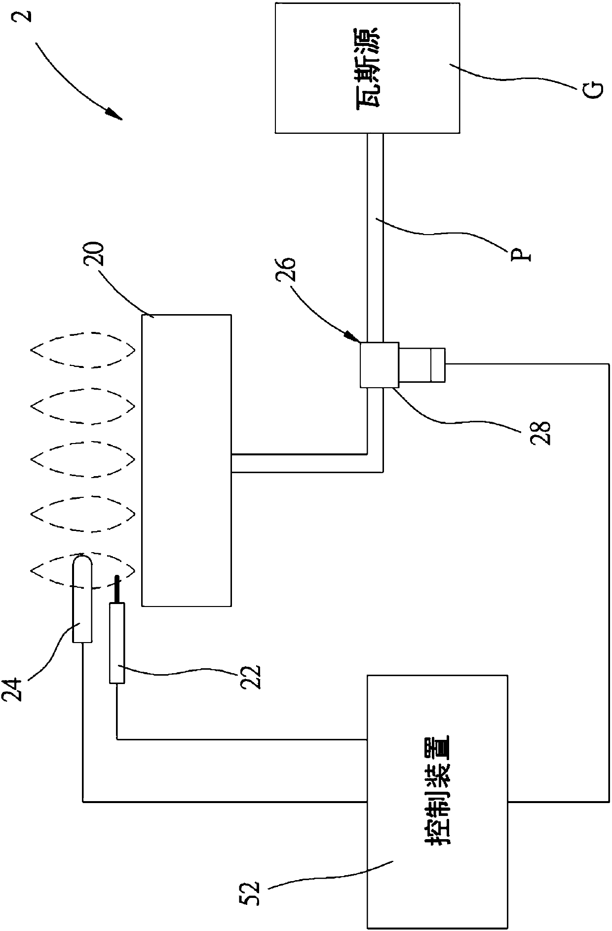
[0056] In order to illustrate the present invention more clearly, preferred embodiments are given and detailed descriptions are as follows in conjunction with the accompanying drawings. Please refer to Figure 2 to Figure 5 Shown is the gas appliance 2 of the first preferred embodiment of the present invention, including a burner 20, an igniter 22, a flame detection element 24, a gas valve 26 and a control device 52, the gas appliance 2 in this embodiment It can be any gas heating device such as gas stove, fireplace, water heater, etc.

[0057] The burner 20 is used to burn gas to generate flame. The igniter 22 is located beside the burner 20 , and the igniter 22 is controlled to generate a spark relative to the burner 20 to ignite the gas output from the burner 20 . The flame detection element 24 is located beside the burner 20 for detecting flames, and the flame detection element 24 can be a thermocouple or a flame sensing needle.

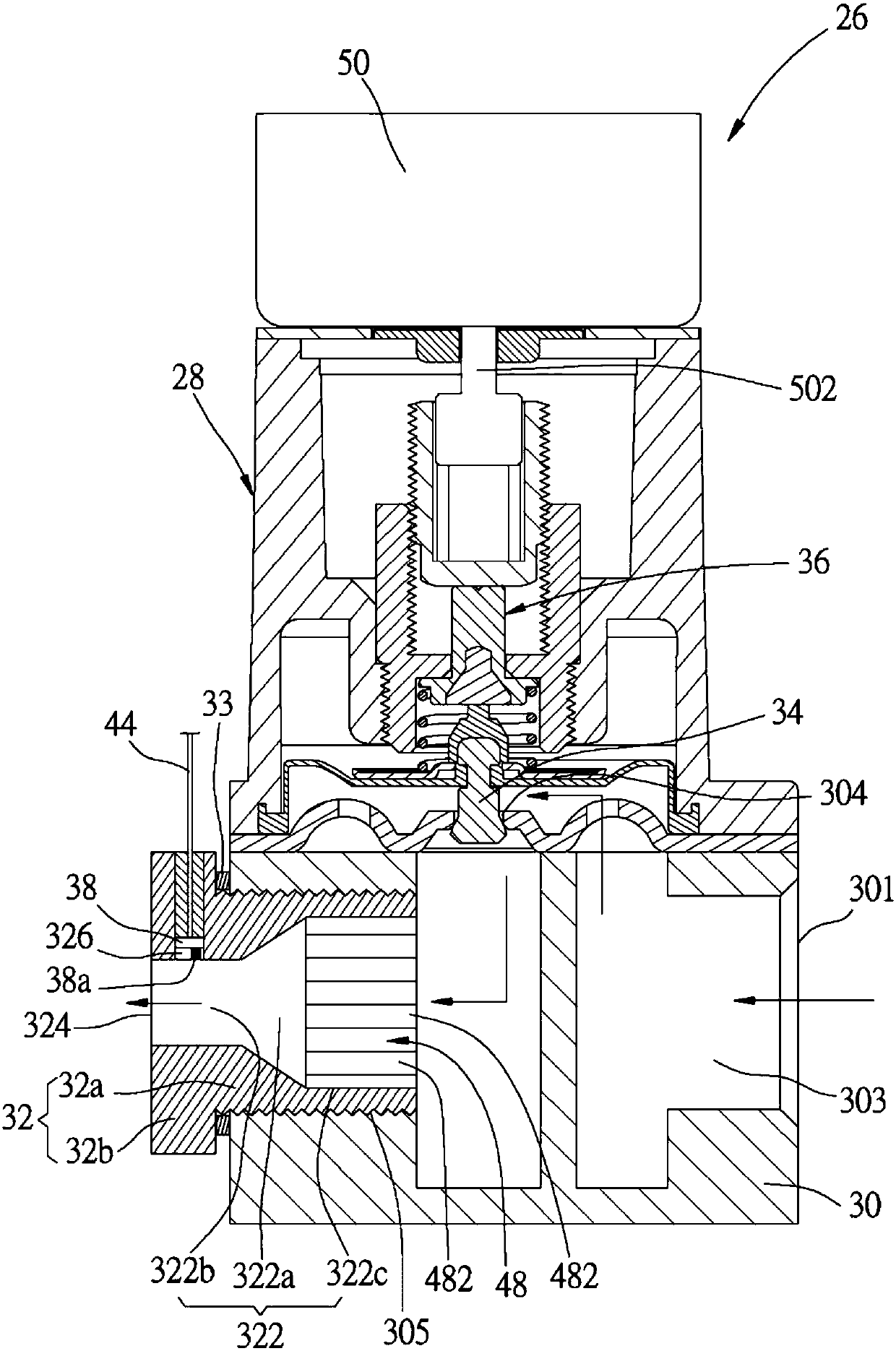
[0058]The gas valve 26 is arranged on a...


PUM


Abstract

A gas appliance comprises a burner, a gas valve and a control device, wherein the gas valve comprises a valve body, a flow adjusting piece, a hot film type flow detecting element and a stepping motor,the valve body communicates with the burner and a gas source, and the flow adjusting piece is driven by the stepping motor to change the flow of gas flowing to the burner. The hot film type flow detecting element is arranged on the valve body and has a detecting end exposed to a gas outlet channel. The control device executes a control method of the gas valve and detects the gas flow of the gas outlet channel through the flow detecting element; the measured gas flow is compared with the preset gas flow, and the stepping motor is controlled to drive the flow adjusting piece according to the comparison result, so that the gas flow measured by the flow detecting element is maintained at the preset gas flow. Therefore, the gas flow can be maintained to be stable.

Description

technical field [0001] The invention relates to gas appliances; in particular, it refers to a gas appliance capable of stabilizing gas flow, a gas valve and a control method thereof. Background technique [0002] Gas appliances are most commonly used in heating devices. Compared with electric heating devices, the heat energy generated by burning gas is greater than that generated by using electricity, and the heating time and reaction time are faster than electric heating devices. [0003] The existing gas appliance 1 includes a burner 10 , a gas valve 12 and a pressure regulator 14 (regulator or pressure stabilizer). The burner 10 is used to burn gas to generate a flame; the gas valve 12 is connected to the burner 10 for manually or electrically adjusting the gas flow output to the burner 10; one end of the pressure regulator 14 is connected to the gas valve 12, and the other end is connected to a Gas source 16 (such as a liquid gas barrel or a natural gas gas pipe). [0...

Claims


Application Information

Patent Timeline
Patent Type & Authority Applications(China)
IPC IPC(8): F16K17/20F16K31/02F16K37/00F23D14/00F23N5/00
CPCF16K17/20F16K31/02F16K37/005F23D14/00F23N5/00
Inventor 黄重景黄锦颖黄信铭黄信雄叶严仁
Owner GRAND MATE
Why Eureka
Try Eureka