Full-automatic contact type measuring equipment and method

A contact measurement and contact technology, applied in the field of automatic contact measurement equipment, can solve the problems of inability to fully reflect the geometric dimensions of the workpiece, interference of optical measurement results, and inability to measure the side and bottom surfaces.

Active Publication Date: 2019-10-08
SHANGHAI JIAO TONG UNIV +1
View PDF11 Cites 17 Cited by
  • Summary
  • Abstract
  • Description
  • Claims
  • Application Information

AI Technical Summary

Problems solved by technology

[0004] 1. There are usually pores and burrs on the surface of the workpiece, which interfere with the optical measurement results;
[0005] 2. This solution can only scan the upper surface of the workpiece, ...

Method used


Image

  • Full-automatic contact type measuring equipment and method
  • Full-automatic contact type measuring equipment and method
  • Full-automatic contact type measuring equipment and method

Examples


Embodiment 1

[0132] Typical measurement workpieces are attached Figure 7 As shown, the thickness direction of the workpiece is A surface and B surface, and there are 9 measuring points relative to each other, that is, A1~A9; the length direction is E surface and F surface, and there are four measuring points, namely E3~E6; perpendicular to The direction of E surface and F surface pointing to the inside of the workpiece is recorded as L-, and the direction pointing to the outside of the workpiece is recorded as L+; the width direction is C surface and D surface, and there are four measuring points arranged opposite to each other, namely C3~C6; In addition, on the workpiece At the corner of the length and width of the workpiece, parallel to the length and width, the surface is offset by a certain distance inside the workpiece, thus forming four corners. The depth of the corner along the length is recorded as the corner length, and the depth of the corner along the width is recorded as the an...

Embodiment 2

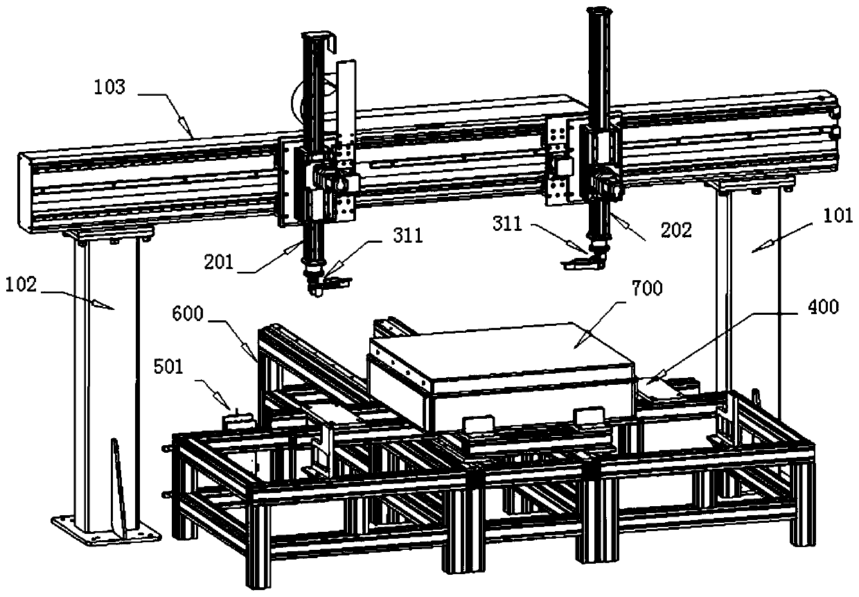
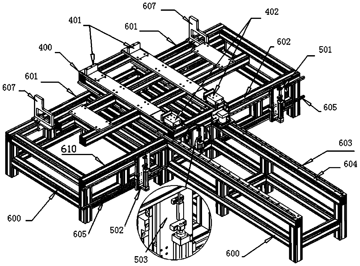
[0237] A measuring arm is arranged on the beam 103 of the automatic contact measuring machine, and a multi-directional contact displacement sensor 303 is arranged on the measuring arm. Among them, the multi-directional contact displacement sensor 303 can rotate and swing, and a jacking measurement section is arranged in the middle of the test bench 600, and the jacking measurement section also includes a lateral movement drive assembly 205, which uses a servo motor to drive the jack. The lifting measuring part can accurately locate the position of any measuring point on the B surface of the workpiece within the length range of the workpiece by traversing the guide rail group along the X direction. A contact displacement sensor in the Z+ direction is arranged on the jacking measuring part.

[0238] In particular, the orientations of the rotary motor 309 and the swing motor 307 corresponding to the contacts of the contact displacement sensor in different directions are defined a...


PUM


Abstract

The invention relates to full-automatic contact type measuring equipment and method. The full-automatic contact type measuring equipment comprises a test bench, a longitudinal sliding table and a cross beam, wherein the longitudinal sliding table is longitudinally and slidably arranged on the test bench and can be used for fixedly placing a measured workpiece, the cross beam is suspended above thetest bench, and at least one measuring arm which can move back and forth along the cross beam is arranged on the cross beam. Compared with the prior art, the equipment in the invention is the equipment specially for rapid and high-precision measurement of the geometric dimension of the large-size workpieces with pores and burrs on the surface, the size of the workpiece is measured by means of a contact type displacement sensor, the defects of the existing measuring method are avoided, so that the influence of the pores and burrs on the surface of the workpiece on precision can be avoided by the measuring equipment, the measurement of the large-size workpiece is more efficient and accurate, relatively complicated workpiece shapes can be adapted to, various dimensions of the thickness, theperpendicularity, the parallelism, the flatness and the like can be measured; meanwhile, the cost of the measuring equipment is lower, and the maintenance and the calibration are simpler and more convenient.

Description

technical field [0001] The invention belongs to the technical field of part surface dimension measurement, and relates to a fully automatic contact measurement device and method. Background technique [0002] It is usually difficult to ensure the accuracy and efficiency of multi-point measurement of length, width, height and other dimensions of large-scale porous material workpieces with rough surfaces. In the actual production of such workpieces, most of them use manual measurement. The disadvantages are that the human measurement error is large, the measurement efficiency is low, and the labor intensity is high. Generally, only random inspection can be realized, and there is a risk of quality loss. In addition, the traditional three-coordinate measuring equipment obtains the size of the workpiece by recording the position where the sensor touches the workpiece, which requires the equipment itself to ensure high dimensional accuracy at each measurement position, making trad...

Claims


Application Information

Patent Timeline
IPC IPC(8): G01B21/02G01B21/08G01B21/18G01B21/30G01B21/22G01B21/24
CPCG01B21/02G01B21/08G01B21/18G01B21/22G01B21/24G01B21/30
Inventor 蒋知峰孔谅周春立金鑫梁诚张立中张悦冯炜杰
Owner SHANGHAI JIAO TONG UNIV
Why Eureka
Try Eureka