Image noise detection method, terminal and storage medium
A detection method and image noise technology, applied in the field of image processing, can solve problems such as large depth image errors, and achieve the effect of reducing errors
- Summary
- Abstract
- Description
- Claims
- Application Information
AI Technical Summary
Problems solved by technology
Method used
Image

Examples
Embodiment 1
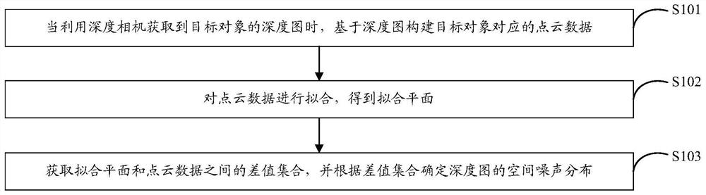
[0059] The embodiment of the present application provides an image noise detection method, such as figure 1 As shown, the method can include:
[0060] S101. When a depth map of a target object is obtained by using a depth camera, construct point cloud data corresponding to the target object based on the depth map.
[0061] An image noise detection method provided by an embodiment of the present application is suitable for a scene where noise detection is performed on a depth map captured by a depth camera.
[0062]In the embodiment of the present application, the terminal uses the depth camera to photograph the target object, and uses the depth camera to obtain the depth map of the target object, and then the terminal constructs point cloud data corresponding to the target object based on the depth map.
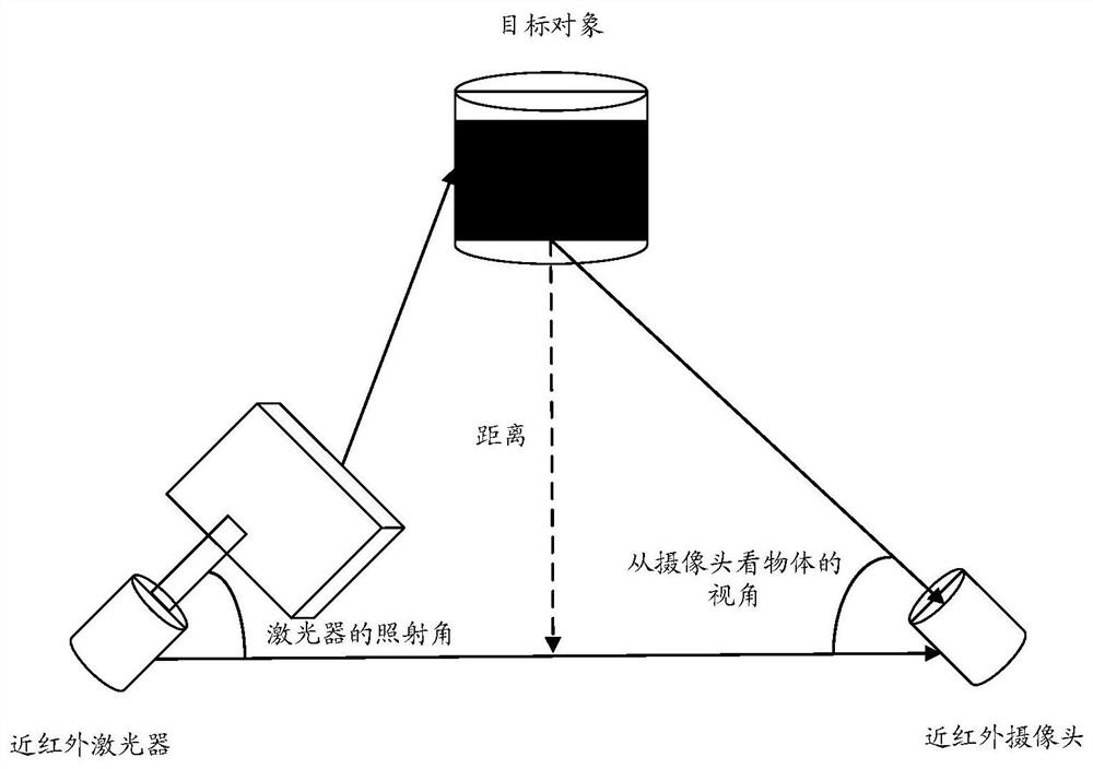
[0063] In the embodiment of the present application, the depth camera may include at least one of a structured light device, a time-of-flight TOF device, and a binocular dev...
Embodiment 2
[0090] The embodiment of the present application provides an image noise detection method, such as Figure 5 As shown, the method can include:
[0091] S201. When the terminal obtains the depth map of the target object by using the depth camera, the terminal performs equidistant sampling on the depth map to obtain a two-dimensional sampling point set corresponding to the target object.
[0092] An image noise detection method provided by an embodiment of the present application is suitable for a scene where noise detection is performed on a depth map captured by a depth camera.
[0093] S202. The terminal constructs point cloud data according to the two-dimensional sampling point set and the depth map.
[0094] After the terminal performs equidistant sampling on the depth map and obtains the two-dimensional sampling point set corresponding to the target object, the terminal constructs point cloud data according to the two-dimensional sampling point set and the depth map.
[...
Embodiment 3
[0114] This embodiment of the present application provides a terminal 1, such as Image 6 As shown, the terminal 1 may include:
[0115] A construction unit 10, configured to construct point cloud data corresponding to the target object based on the depth map when the depth map of the target object is obtained by using the depth camera;
[0116] a plane fitting unit 11, for fitting the point cloud data to obtain a fitting plane;
[0117] A determination unit 12, configured to acquire a difference value set between the fitting plane and the point cloud data, and determine the spatial noise distribution of the depth map according to the difference value set.
[0118] Optionally, the terminal further includes: a sampling unit 13;
[0119] The sampling unit 13 is configured to perform equidistant sampling on the depth map to obtain a two-dimensional sampling point set corresponding to the target object;
[0120] The construction unit 10 is specifically configured to construct t...
PUM
 Abstract
Description
Claims
Application Information
 - R&D
- Intellectual Property
- Life Sciences
- Materials
- Tech Scout
- Unparalleled Data Quality
- Higher Quality Content
- 60% Fewer Hallucinations
Browse by: Latest US Patents, China's latest patents, Technical Efficacy Thesaurus, Application Domain, Technology Topic, Popular Technical Reports.
© 2025 PatSnap. All rights reserved.Legal|Privacy policy|Modern Slavery Act Transparency Statement|Sitemap|About US| Contact US: help@patsnap.com