Rotating electric machine

A technology for rotating electrical machines and rotors, which is applied in the direction of motors, electromechanical devices, electric vehicles, etc., and can solve problems such as inability to ensure oil flow rate, oil entry, and uneven cooling of coils

Inactive Publication Date: 2019-10-08
HONDA MOTOR CO LTD
View PDF7 Cites 0 Cited by
  • Summary
  • Abstract
  • Description
  • Claims
  • Application Information

AI Technical Summary

Problems solved by technology

[0007] However, in the technique described in the above-mentioned Patent Document 1, if the flow velocity of the oil released from the oil hole cannot be ensured, there is a possibility that the root portion of the coil end portion located near the stator core may be partially pumped from the inner side in the radial direction. ground supply of refrigerant
In this case, uneven cooling of the coil may occur
Therefore, in the pr

Method used


Image

  • Rotating electric machine
  • Rotating electric machine
  • Rotating electric machine

Examples


Embodiment Construction

[0046] Hereinafter, embodiments of the present invention will be described based on the drawings.

[0047]

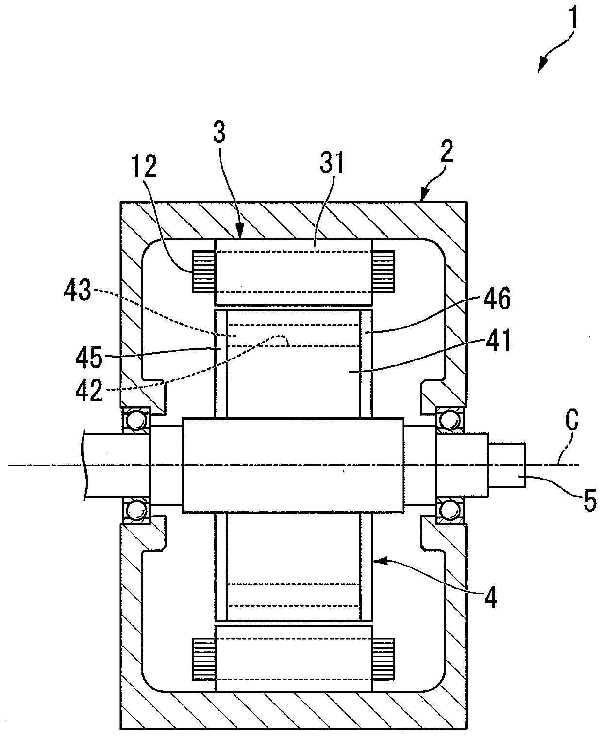
[0048] figure 1 It is a cross-sectional view showing a schematic configuration of the rotating electrical machine of the embodiment.

[0049] figure 1 The rotating electric machine 1 shown is, for example, a running motor mounted in a vehicle such as a hybrid vehicle or an electric vehicle. However, the configuration of the present invention is not limited to traveling motors, and can be applied to motors for power generation, motors for other purposes, and rotating electric machines (including generators) other than vehicles.

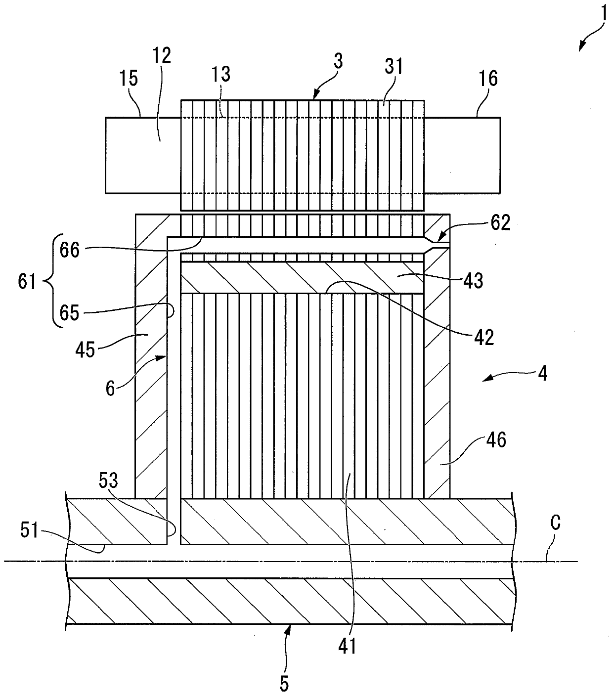
[0050] The rotary electric machine 1 includes a case 2, a stator 3, a rotor 4, an output shaft 5, and a refrigerant flow path 6 (see figure 2 ).

[0051] The casing 2 accommodates the stator 3 , the rotor 4 and the output shaft 5 . Refrigerant (not shown) is accommodated inside the casing 2 . The above-mentioned stator 3 is arranged in a ...


PUM


Abstract

The present invention provides a rotary electric machine capable of expanding a wetted area to a coil end portion, uniformly cooling the coil end portion, and suppressing an increase in friction. Therotating electric machine includes a stator (3) having a cylindrical stator core (31) and a coil (12) assembled on the stator core (31); and a rotor (4), which is configured to be able to rotate in adiameter relative to the stator (3). Rotating inward; and a refrigerant flow path (6), which is provided in the rotor (4) and allows the refrigerant to circulate as the rotor (4) rotates. The refrigerant flow path (6) has a rotor internal flow path (61) formed inside the rotor (4) and a direction communicating with the rotor internal flow path (61) and extending in a direction facing the central axis (C) of the rotor (4). The nozzle section (62) opened on the end face of the nozzle has a cross-sectional area smaller than that of the internal flow path (61) of the rotor in a cross section perpendicular to the flow direction of the refrigerant.

Description

technical field [0001] This invention relates to rotating electric machines. Background technique [0002] Conventionally, a rotating electric machine has been used as a power source of a hybrid vehicle or an electric vehicle. In a rotating electrical machine, a magnetic field is formed in a stator core by supplying a current to a coil, and magnetic attraction and repulsion are generated between the permanent magnets of the rotor and the stator core. Thus, the rotor rotates relative to the stator. [0003] In addition, especially during high-load operation, when current flows through the coils of the stator, the coils generate heat due to copper loss. The heat generated by the coil is a factor that degrades the performance of the rotating electric machine. Therefore, various techniques for cooling the coils of the stator have been proposed. [0004] For example, in Patent Document 1 (Japanese Unexamined Patent Publication No. 9-182374), it is described that an axial oil ...

Claims


Application Information

Patent Timeline
IPC IPC(8): H02K9/19H02K3/24
CPCH02K3/24H02K9/19Y02T10/64
Inventor 山口健太郎
Owner HONDA MOTOR CO LTD
Why Eureka
Try Eureka