Supercharge Your Innovation With Domain-Expert AI Agents!

Quick-change pulse current processing and laser shock foil compound replaceable die micro-forming device and method

A pulse current and laser shock technology, which is applied in laser welding equipment, metal processing equipment, welding equipment, etc., can solve the problems of cumbersome disassembly process, complicated pressing method, and inability to replace the die, so as to improve the forming quality and plastic deformation. Effects of capacity improvement and flow stress reduction

Active Publication Date: 2021-06-22
JIANGSU UNIV
View PDF9 Cites 0 Cited by
  • Summary
  • Abstract
  • Description
  • Claims
  • Application Information

AI Technical Summary

Problems solved by technology

However, this method only uses laser shock as a processing technology. Due to the limitation of the structure of the device itself, it is impossible to efficiently replace the die, and the pressing method is relatively complicated, and it needs to rely on multiple bolts to connect and fix the clamping device. , so the disassembly process after the processing is completed is relatively cumbersome, that is, the interval between two adjacent processing cycles is relatively long

Method used


Image

  • Quick-change pulse current processing and laser shock foil compound replaceable die micro-forming device and method
  • Quick-change pulse current processing and laser shock foil compound replaceable die micro-forming device and method
  • Quick-change pulse current processing and laser shock foil compound replaceable die micro-forming device and method

Examples


Embodiment Construction

[0048] Embodiments of the present invention are described in detail below, examples of which are shown in the drawings, wherein the same or similar reference numerals designate the same or similar elements or elements having the same or similar functions throughout. The embodiments described below by referring to the figures are exemplary and are intended to explain the present invention and should not be construed as limiting the present invention.

[0049] In describing the present invention, it is to be understood that the terms "central", "longitudinal", "transverse", "length", "width", "thickness", "upper", "lower", "axial", The orientation or positional relationship indicated by "radial", "vertical", "horizontal", "inner", "outer", etc. is based on the orientation or positional relationship shown in the drawings, and is only for the convenience of describing the present invention and simplifying the description , rather than indicating or implying that the device or elem...


PUM


Abstract

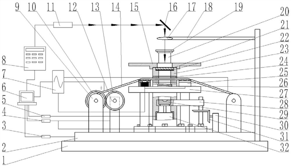
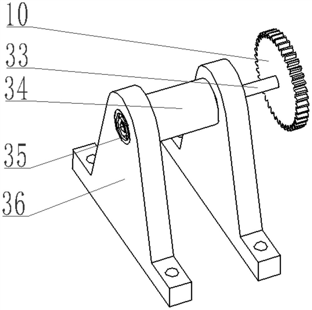
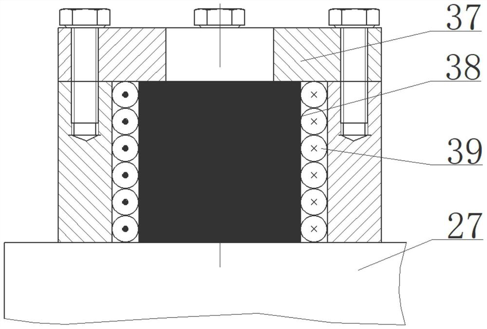
The invention discloses a quick-change type pulse current processing and laser shock foil composite replaceable die microforming device and its method, and relates to the technical field of advanced manufacturing micro parts. The device includes a laser emitting system, a control system and micro part forming system; the laser emission system is used to generate laser light, and the control system is used to control the work of the forming device; the micro-forming system is used for workpiece forming; the micro-part forming system includes a pressing plate, a cavity and a supporting platform; The magnetic suction device is used to realize the rapid compression of the device, and then the metal foil is punched through the cylinder, and then the pulse laser is used as the energy source, and the plasma explosion is used to generate the impact force, so as to realize the forming of the foil, and finally the part is punched through the cylinder. The ejection and cylinder reset and the rolling material of the coil device realize the rapid replacement of workpieces, and at the same time, the die replacement device can be used to realize the rapid replacement of dies; the invention can complete the forming of metal micro parts at one station.

Description

technical field [0001] The invention relates to the technical field of advanced manufacturing micro-parts, in particular to a quick-change pulse current processing and laser shock foil composite replaceable die micro-forming device and method thereof. Background technique [0002] With the rapid development of today's productivity, especially in the field of aerospace and automobile manufacturing, the requirements for the strength and manufacturing accuracy of micro-parts with micro-features are also getting higher and higher, so a high-precision, high-quality micro-forming Process to ensure the precision of workpiece forming. Laser shock microforming is a processing method that uses laser energy as the shock source to instantly cause plastic deformation of the workpiece, which can form micro parts with better quality and higher precision. [0003] Relevant studies have shown that electroplastic effects can be produced on metal materials by applying pulse currents to them. ...

Claims


Application Information

Patent Timeline
Patent Type & Authority Patents(China)
IPC IPC(8): B23K26/356B23K26/60B23K26/70
CPCB23K26/356B23K26/60B23K26/702
Inventor 张浩堃王霄陆家鑫顾鑫王科阳刘会霞
Owner JIANGSU UNIV
Features
  • R&D
  • Intellectual Property
  • Life Sciences
  • Materials
  • Tech Scout
  • Unparalleled Data Quality
  • Higher Quality Content
  • 60% Fewer Hallucinations
Learn More