[0033] The specific embodiment of the present invention will be described in further detail by describing the embodiments below with reference to the accompanying drawings, the purpose is to help those skilled in the art to have a more complete, accurate and in-depth understanding of the concept and technical solutions of the present invention, and contribute to its implementation.
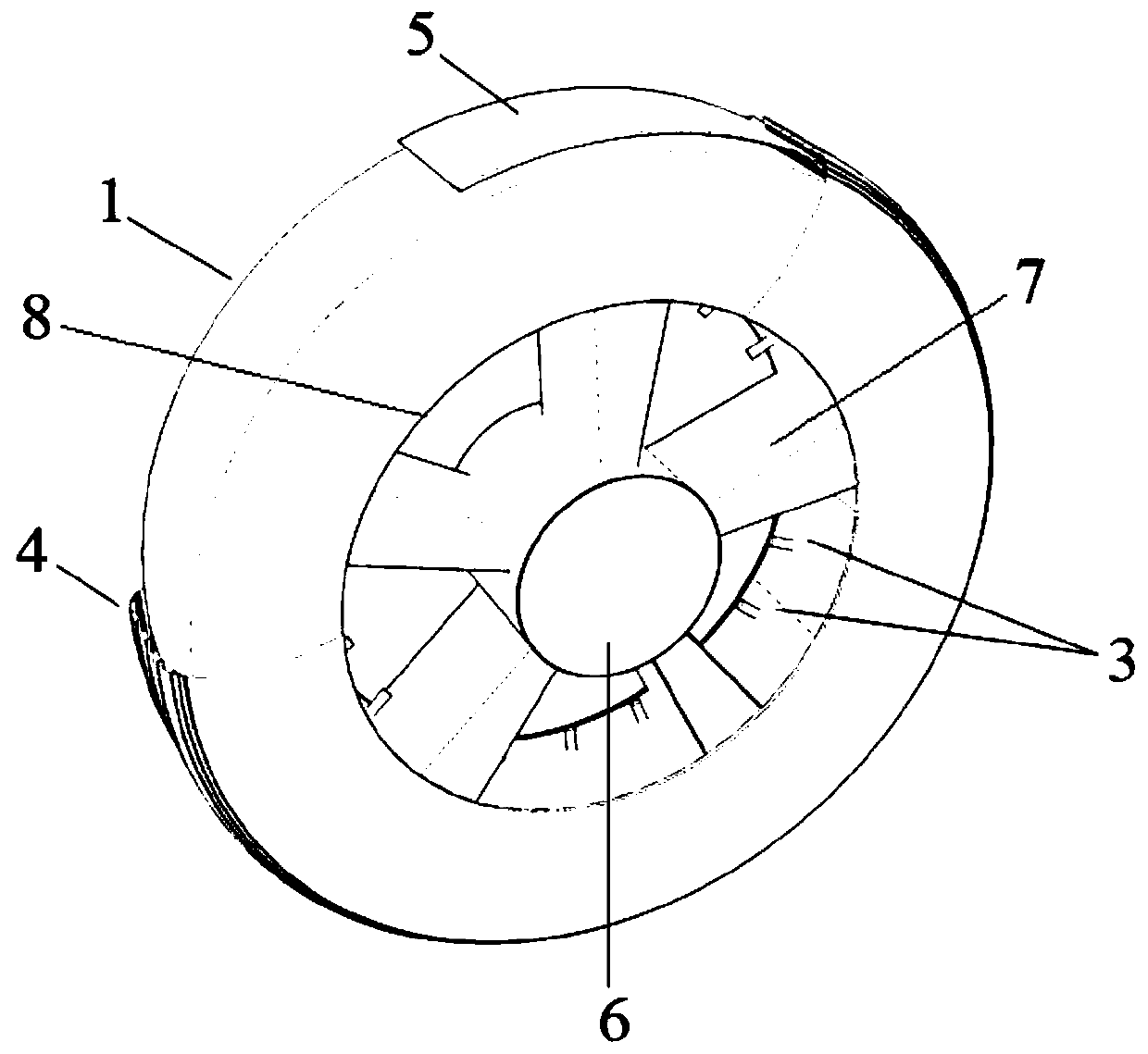
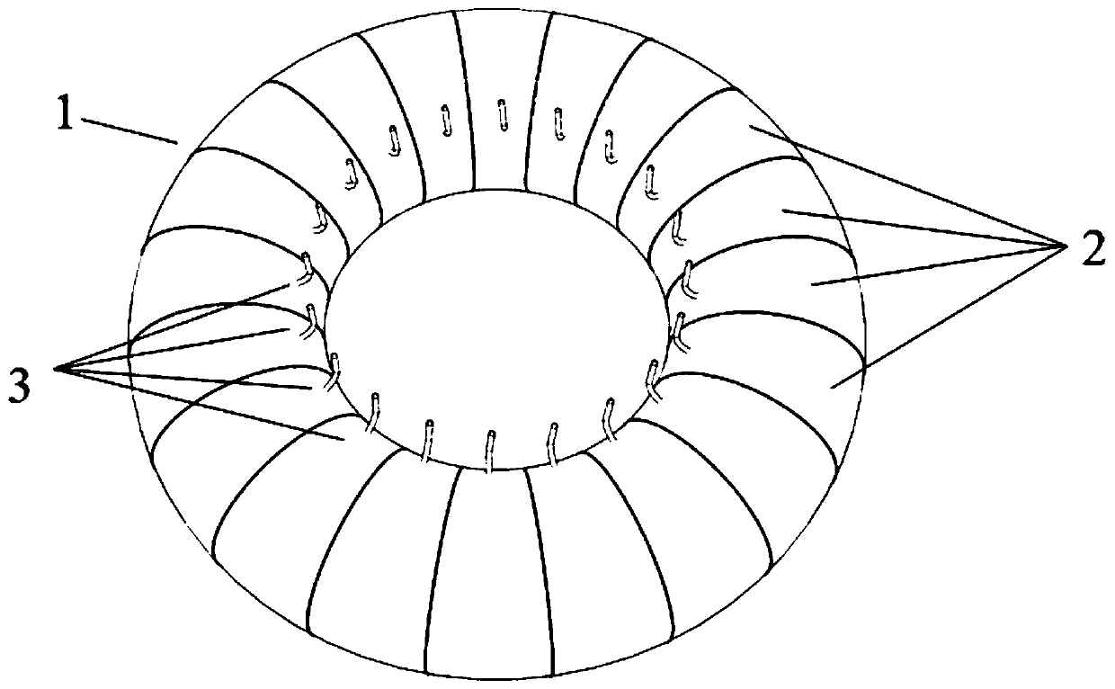
[0034] like figure 1 and figure 2 As shown, the present invention provides a commercial vehicle run-flat tire assembly, comprising a rigid wheel, a pad 5, a cover tire 4 arranged on the rigid wheel, an inner tube 1 arranged inside the cover tire 4 and a diaphragm 2 arranged inside the inner tube 1 , the diaphragm 2 divides the inner cavity of the inner tube 1 into a plurality of independent air storage chambers, and two adjacent air storage chambers are not connected.
[0035] Specifically, as figure 1 and figure 2 As shown, the rigid wheel mainly includes a rim 8, a hub 6 and a spoke 7, the rim 8 and the hub 6 are arranged coaxially, the hub 6 is located at the center of the rim 8, the spoke 7 is located between the rim 8 and the hub 6 and the spoke 7 and the rim 8 is fixedly connected with wheel hub 6. The inner tire 1 is placed on the rim 8, and the inner tire 1 is covered with a cushion belt 5, and the cushion belt 5 and the inner tire 1 are wrapped by a cover tire 4, and the cover tire 4 is installed on the rim 8 to form a commercial vehicle explosion-proof tire assembly. There are multiple diaphragms 2 and all the diaphragms 2 are evenly distributed along the circumferential direction inside the inner tube 1. There are 24 to 36 air storage chambers in total. All the air storage chambers are evenly distributed along the circumferential direction of the inner tube 1. Two adjacent air storage chambers The cavity is separated by a diaphragm 2, and gas is stored in the gas storage cavity. Air nozzles 3 for charging gas into the air storage chambers are provided at positions corresponding to each air storage chamber on the inner tube 1, and the rigid wheel has an air nozzle hole for the air nozzle 3 to pass through.
[0036] like figure 1 and figure 2 As shown, the number of the air nozzle 3 is the same as the number of the air storage cavity, the air nozzle hole is a through hole on the rim 8 along the radial direction of the rim 8, one end of the air nozzle 3 is fixedly connected with the inner tube 1, and the air nozzle 3 The other end of the air nozzle passes through the air nozzle hole, which is convenient for the inflatable device to inflate. The number of gas nozzle holes is the same as the number of gas nozzles 3, and all the gas nozzle holes on the rim 8 are evenly distributed along the circumferential direction, and a gas nozzle 3 is respectively inserted in each gas nozzle hole, and each gas nozzle 3 is used to supply to a storage tank respectively. Inflate the air cavity.
[0037] Both the inner tube 1 and the diaphragm 2 are integrally pressed and formed of the same rubber material. The manufacturing process is simple, and there is no risk of safety hazards such as parts falling off during long-term driving. The diaphragm 2 is made of rubber, and the tire noise is small during driving. High comfort. An air nozzle 3 is set at each air storage cavity, and all compartments are inflated at the same time through a special inflator to ensure that the tire pressure of each compartment is consistent and the vehicle is safe to drive. Inner tube 1, diaphragm 2, air nozzle 3, and air nozzle holes are evenly distributed on the outer circumference of the tire, so that the mass distribution of the run-flat tire assembly for commercial vehicles is even, ensuring the stability of the vehicle at high speed and the dynamic balance of the vehicle. The inner tube 1 is inflated to the standard tire pressure by a special inflation device, and assembled on the corresponding position of the body of the commercial vehicle. When the vehicle is running, if a sharp object is punctured or a certain part of the inner tube 1 is too strong to support the internal tire pressure, a tire blowout occurs, and the gas in the corresponding part of the gas storage chamber leaks rapidly. The inside of the inner tube 1 is divided into 24 to 36 independent air storage chambers by the diaphragm 2. At the moment of tire blowout, only one compartment leaks gas and loses support to the vehicle body, while the other compartments can still continue to support the weight of the vehicle body, so that the driving direction of the car will not change. Sudden and large deviation from the original driving direction, it is easy for the driver to control the direction of the vehicle. After a puncture, the vehicle will not stop immediately under the action of inertia, and the tire will continue to roll forward to bear part of the body pressure, and part of the pressure acts on the diaphragm 2 on both sides of the puncture section; and the high-pressure gas in the puncture section leaks from the rear tire Pressure is identical with atmospheric pressure, and its adjacent partition is still high pressure, and pressure difference also acts on the diaphragm 2 of the tire burst partition both sides. If the vehicle is lighter, the pressure on the diaphragm 2 on both sides of the burst tire compartment does not exceed its limit value, and the vehicle will bump forward; if the vehicle is heavier, the pressure on the diaphragm 2 on both sides of the burst tire compartment exceeds its limit limit value, then the adjacent partitions of the inner tube 1 will rupture and blow out successively. The inside of the inner tube 1 is divided into 24 to 36 sections by the diaphragm 2. When the sections are broken sequentially, the amount of gas released by each section is relatively small, the impact force generated by the rupture is small, and the impact on the driving stability of the vehicle is also small. Can cause loss of control of the vehicle. Regardless of which of the above two situations occurs after a puncture, the commercial vehicle run-flat tire assembly can effectively reduce the impact of the puncture on the vehicle, without causing drastic changes in the direction of the vehicle and delaying the deterioration of the accident. Provide emergency response time for drivers and commercial vehicle tire puncture control systems.
[0038] like image 3 As shown, the present invention also provides a commercial vehicle tire blowout control system, including ECU (Electronic Control Unit electronic control unit, also known as "travel computer"), wheels, braking system and steering system, and the wheels adopt the commercial vehicle of the above structure Run-flat tire assembly. The wheels of commercial vehicles include left front wheels, right front wheels, left rear wheels and right rear wheels.
[0039] The braking system includes a vacuum booster, a brake master cylinder, a combined brake valve, brakes and an ABS system (antilockbrake system, anti-lock braking system). The ABS system includes a wheel speed sensor and has an ABS anti-lock function. Steering system includes steering ECU, steering sensor and steering motor. ECU and steering ECU flash the tire blowout control program. The ABS system adopts three-channel or four-channel type. The commercial vehicle tire blowout control system is used in conjunction with the commercial vehicle run-flat tire assembly.
[0040] After the vehicle is started, the commercial vehicle tire blowout control system starts to work. The wheel speed sensor of the ABS system monitors the wheel speed in real time. If the wheel speed difference exceeds the blowout threshold, the ECU will judge whether a blowout has occurred. If only the wheel speed is abnormal but no tire blowout occurs, the alarm will remind the driver to stop and check.
[0041] If the wheel speed difference exceeds the puncture threshold, the ECU will determine that a puncture has occurred, and the ECU will control the vehicle to turn on the double flashing lights to warn the surrounding vehicles; the ECU will determine whether the front tire of the vehicle is punctured according to the wheel speed, and if "No", it will be The rear tire blew out.
[0042] After the ECU determines that the vehicle has a tire blowout, the steering ECU intervenes. The steering sensor monitors the driver's steering operation. The ECU determines that the driver has not performed a steering operation, and the ECU controls the braking system to actively intervene to assist the driver in braking the vehicle. The working process of the braking system is: brake pedal—vacuum booster amplification/ECU intervention—push the brake master cylinder - pressurize the brake fluid - distribute the brake combination valve - brake the brake, and at the same time, the anti-lock function of the ABS system is passively involved.
[0043] If the steering ECU determines that the driver has performed a steering operation, the ECU intervenes to control the steering system to lock the driver's control of the vehicle's driving direction, and the ECU controls the braking system to actively intervene to brake the vehicle. The working process of the braking system is as follows: : ECU intervenes in the vacuum booster—promotes the master cylinder—pressurizes the brake fluid—distributes the combined brake valve—brakes, and at the same time, the anti-lock function of the ABS system is passively involved. The ECU judges "Yes" according to the wheel speed, and the front tire blows out, then the steering ECU intervenes, the steering sensor monitors the driver's operation on the steering, and the threshold value set by the steering ECU program determines whether to change the vehicle's driving trajectory by slamming the direction.
[0044] If the steering ECU program determines that the driver has not slammed the steering wheel, the ECU controls the braking system to actively intervene to assist the driver in braking. The working process is: brake pedal—vacuum booster amplification/ECU intervention—push the master cylinder—pair Brake fluid pressurization-brake combined valve distribution-brake braking, and the anti-lock function of the ABS system is passively involved.
[0045] If the steering ECU determines that the driver has performed a steering operation, the ECU will determine whether the left front wheel has a puncture according to the wheel speed. If "No", it means that the right front wheel has a puncture. Dynamically correct the driving direction of the vehicle to the left so that the vehicle continues to move forward in the original driving direction. At the same time, the ECU controls the braking system to actively intervene in the braking of the vehicle. Hydraulic pressurization-brake combined valve distribution-brake braking, while the anti-lock function of the ABS system is passively involved.
[0046] If the ECU judges according to the wheel speed that the left front wheel has blown out, the ECU intervenes to control the steering motor of the steering system to dynamically correct the vehicle's driving direction to the right according to the real-time vehicle speed, so that the vehicle continues to move forward in the original driving direction, and at the same time, the ECU controls the braking system to actively intervene to correct The working process of vehicle braking is: ECU intervenes in the vacuum booster - pushes the brake master cylinder - pressurizes the brake fluid - distributes the brake combination valve - brakes, and at the same time the anti-lock function of the ABS system is passively involved.
[0047] The vehicle brakes to a stop, and the commercial vehicle tire blowout control system ends.
[0048] The commercial vehicle tire blowout control system considers the current situation of low configuration of commercial vehicles, follows the principle of "give speed and don't give way", try to keep the vehicle braking in the original driving direction after a tire blowout, and avoid rapid steering to avoid other vehicles when driving at high speed More serious accidents such as loss of control of the vehicle, rollover, and collision with other lane vehicles. Make full use of the functions of the braking system, ECU, and steering system; when the vehicle's wheel speed is abnormal, it will alarm the driver. Quickly judge the specific wheel that has a puncture, and adopt different coping methods for the different characteristics of the vehicle's front and rear tire puncture; and can monitor whether the driver's steering is appropriate through the steering sensor. When the operation is appropriate, the ECU controls the braking system to actively intervene and assist The driver brakes; when the operation is improper, the ECU controls the steering system and the braking system actively intervenes to correct the vehicle's driving direction and brake according to the real-time vehicle speed.
[0049] The above-mentioned commercial vehicle run-flat tire assembly and commercial vehicle puncture control system cooperate with each other. When a puncture accident occurs, the commercial vehicle run-flat tire assembly ensures that the vehicle is relatively stable on the one hand, and on the other hand provides the driver and the commercial vehicle puncture control system with Valuable emergency treatment time; at the same time, the commercial vehicle tire burst control system can choose a reasonable time to assist braking according to the specific conditions of the vehicle through the cooperation of the tire burst control program and the supporting sensors and actuators, or actively intervene in steering and braking to ensure The vehicle stops safely to ensure the safety of personnel.
[0050] The present invention has been exemplarily described above in conjunction with the accompanying drawings. Obviously, the specific implementation of the present invention is not limited by the above methods, as long as various insubstantial improvements are adopted in the method concept and technical solutions of the present invention, or there is no improvement Directly applying the conception and technical solutions of the present invention to other occasions falls within the protection scope of the present invention.