A river sludge dredging treatment equipment

A technology for treating equipment and sludge, applied in the direction of sludge treatment, water/sludge/sewage treatment, special treatment goals, etc., can solve the difficulty of dismantling, cleaning and installation of the filter belt, without considering the production and manufacturing costs, without taking into account Cleaning and maintenance and other issues to achieve the effect of saving manufacturing costs and improving mud scraping efficiency

Active Publication Date: 2020-07-21
SHANGHAI RUIHUI ENVIRONMENTAL PROTECTION TECH
View PDF5 Cites 0 Cited by
  • Summary
  • Abstract
  • Description
  • Claims
  • Application Information

AI Technical Summary

Problems solved by technology

[0002] With the continuous development of industry, the pollution of river channels is becoming more and more serious. At present, the dredging of rivers has to rely on dredging equipment. The application number 201510814814.3 discloses a sludge filter belt mechanism, which solves the sludge existing in the prior art. The dehydration efficiency and quality are not high. However, under the premise of ensuring the sludge dewatering efficiency, the device does not consider how to clean and maintain later. Disassembling the equipment for internal and filter belt cleaning will greatly increase the cost of equipment. At the same time, this device does not take into account how to reduce the production and manufacturing costs of the equipment at present. The use of multiple rollers to complete the filtration of sludge not only increases the production and manufacturing costs of the equipment, but also makes the follow-up filter belt dismantling and cleaning and installation difficult. difficulty

Method used


Image

  • A river sludge dredging treatment equipment
  • A river sludge dredging treatment equipment
  • A river sludge dredging treatment equipment

Examples


Embodiment Construction

[0035] The following will clearly and completely describe the technical solutions in the embodiments of the present invention with reference to the accompanying drawings in the embodiments of the present invention. Obviously, the described embodiments are only some, not all, embodiments of the present invention. Based on the embodiments of the present invention, all other embodiments obtained by persons of ordinary skill in the art without creative efforts fall within the protection scope of the present invention.

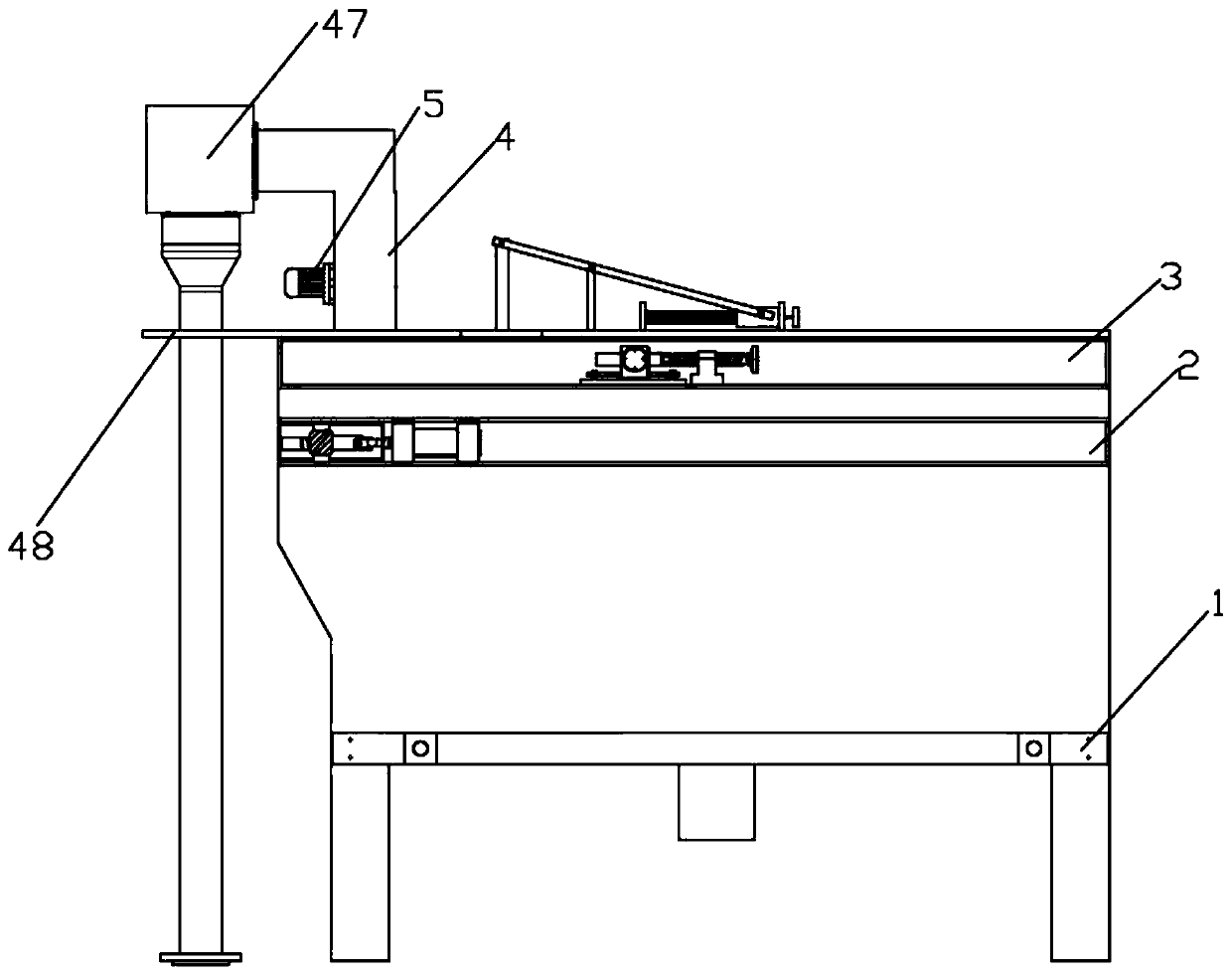
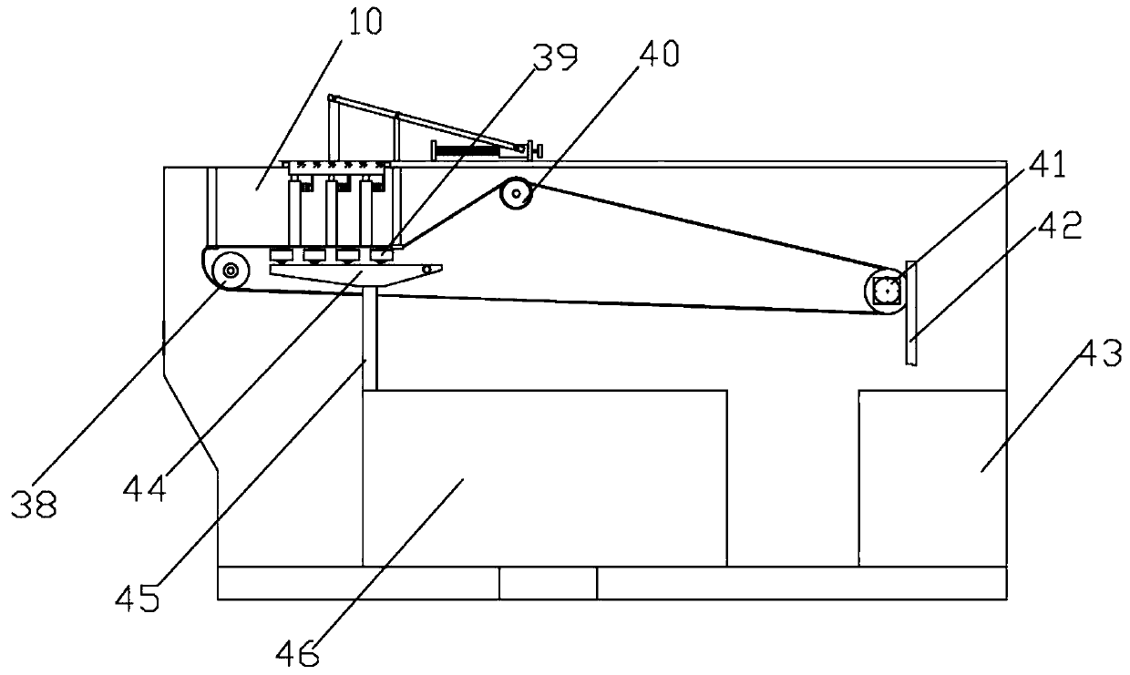
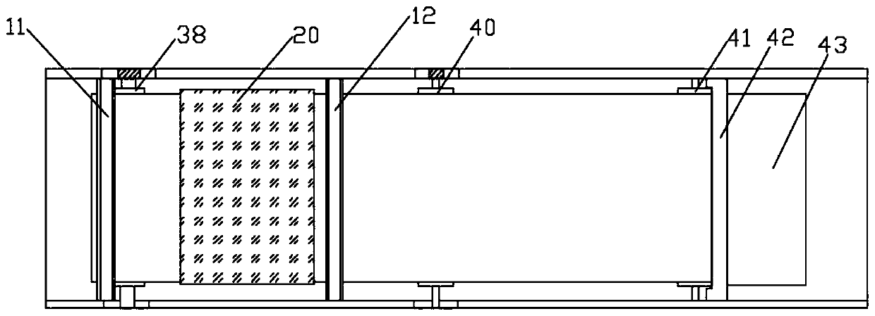
[0036] see Figure 1-8 As shown, the present invention is a kind of river sludge dredging treatment equipment, including equipment main body 1, the outer wall of the same side of equipment main body 1 is respectively fixed with first channel steel 2 and second channel steel 3 from bottom to top, and inside equipment main body 1 The mud scraping chamber 10 is fixedly arranged on the top of the chamber, the mud scraping chamber 10 includes the front fender 11 and the...


PUM


Abstract

The invention discloses watercourse sludge desilting treatment equipment. The device comprises an equipment main body, wherein a first steel channel and a second steel channel are correspondingly fixed on the same side outer wall of the equipment main body from bottom to top, and a mud scraping cavity is fixedly arranged at the top of an inner cavity of the equipment main body; and the mud scraping cavity comprises a front mudguard and a rear mudguard, a movable top cover is arranged on the top of one side of the mud scraping cavity, a first connecting rod which is longitudinally arranged is fixedly connected to the upper end surface of the movable top cover, and a second connecting rod is hinged to one end, far away from the movable top cover, of the first connecting rod. According to thewatercourse sludge desilting treatment equipment, the mud scraping cavity and a filtering belt can be cleaned without dismounting the equipment, so that the cleaning of the equipment is more convenient, and meanwhile, the time cost for cleaning the equipment is saved; and sludge in a sludge inlet pipe is optimized and stirred through a bidirectional motor, the stirring efficiency of the sludge isensured while the use number of stirring blades is reduced, the manufacturing cost of the equipment is saved, and fine sand in the sludge can be effectively prevented from being adsorbed on the surface of the filtering belt so as to affect the water filtering efficiency of the filtering belt.

Description

technical field [0001] The invention relates to the technical field of sludge treatment equipment, in particular to a river sludge dredging treatment equipment. Background technique [0002] With the continuous development of industry, the pollution of river channels is becoming more and more serious. At present, the dredging of rivers has to rely on dredging equipment. The application number 201510814814.3 discloses a sludge filter belt mechanism, which solves the sludge existing in the prior art. The dehydration efficiency and quality are not high. However, under the premise of ensuring the sludge dewatering efficiency, the device does not consider how to clean and maintain later. Disassembling the equipment for internal and filter belt cleaning will greatly increase the cost of equipment. At the same time, this device does not take into account how to reduce the production and manufacturing costs of the equipment at present. The use of multiple rollers to complete the fil...

Claims


Application Information

Patent Timeline
Patent Type & Authority Patents(China)
IPC IPC(8): E02F3/88E02F5/28C02F11/123
CPCC02F11/123C02F2303/14C02F2303/16E02F3/88E02F5/28
Inventor 郭小兵李攀力
Owner SHANGHAI RUIHUI ENVIRONMENTAL PROTECTION TECH
Why Eureka
Try Eureka