Telescopic gas supply pipeline for slender combustion chamber

An air supply pipeline and combustion chamber technology, which is applied in the field of retractable air supply pipelines, can solve the problems such as the inability to effectively adjust the length and position of the gas supply pipeline of the burner, the inability to flexibly adjust the position of the heat source, and the limitation of the structure space of the combustion chamber.

Active Publication Date: 2019-10-11
BEIJING INSTITUTE OF TECHNOLOGYGY
View PDF7 Cites 2 Cited by
  • Summary
  • Abstract
  • Description
  • Claims
  • Application Information

AI Technical Summary

Problems solved by technology

[0006] The purpose of the present invention is to overcome the defects of the prior art, in order to solve the problem that the length and position of the gas supply pipeline of the burner cannot be effectively adjusted due to the l

Method used


Image

  • Telescopic gas supply pipeline for slender combustion chamber
  • Telescopic gas supply pipeline for slender combustion chamber
  • Telescopic gas supply pipeline for slender combustion chamber

Examples


Embodiment

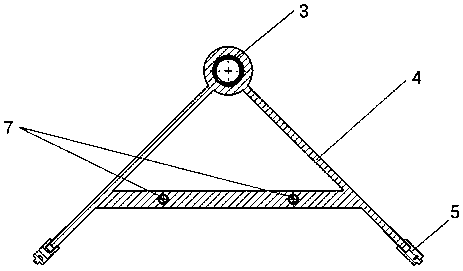
[0067] A telescopic air supply duct for a slender combustion chamber, the structure of which is as follows figure 1 As shown, it includes the outermost pipeline 1, the intermediate pipeline 2, the innermost pipeline 3, the guide structure 4, the support rod 5, the sleeve 6, the smallest diameter guide rod 7, the intermediate grade guide rod 8, the largest diameter guide rod 9, the first Second gear 10, frequency modulation motor 11, motor base 12, first flange 13, first gear 14, first bearing end cover 15, second bearing end cover 16, fixed rod 17, first sealing ring 18 of bearing end cover , The second sealing ring 19 of the bearing cover, the first sealing ring 20 of the pipeline, the second sealing ring 21 of the pipeline, the first cylindrical roller bearing 22 , the second cylindrical roller bearing 23 and the second flange 24 . figure 2 It is a top view of the overall structure of the pipeline.

[0068] Among them, among the outermost pipeline 1 , the intermediate pip...


PUM


Abstract

The invention provides a telescopic gas supply pipeline for a slender combustion chamber, and belongs to the technical field of aerospace propulsion power systems. The telescopic gas supply pipeline for the slender combustion chamber comprises an outermost pipeline, an innermost pipeline, a middle pipeline, a pipeline sealing ring, a guide rod, a guide structure, a driving device and a fixing device. The driving device comprises a frequency modulation motor, a motor base and a gear. The fixing device comprises a bearing end cover, a cylindrical roller bearing, a flange plate, a fixing rod, a sleeve, a bearing end cover sealing ring and a supporting rod. The pipeline can be controlled in a single side, the continuous extension and shortening of the pipeline are achieved in a limited space,the stretching at different speeds and rapid stopping switching can be achieved, and the function switching is rapid. Through screw thread transmission of a screw rod, the telescopic supply is accurate and reliable, and the pipeline has good sealing performance and is suitable for operation and use in a high-pressure environment. The telescopic gas supply pipeline for the slender combustion chamber of the invention is simple in structure, stable in operation and convenient to maintain, and can be simply modified to be suitable for working environments with different depths, lengths and spaces.

Description

technical field [0001] The invention relates to a telescopic air supply pipeline for a slender combustion chamber, belonging to the technical field of aerospace propulsion power systems. Background technique [0002] During the design and use of aerospace engines, thermoacoustic instability is usually faced. Thermoacoustic instability is an unstable phenomenon caused by the mutual coupling and amplification of unstable heat release and sound waves. It involves various aspects such as fluid, combustion, heat transfer, and acoustics, and occurs in various power devices. Its serious destructiveness and strong noise have triggered in-depth research in various aspects. [0003] In 1859, Rijke placed a hot wire mesh at a certain position in the lower half of a pipe (that is, a combustion chamber) that was open at both ends and placed vertically, and immediately there was a strong sound vibration in the pipe. In the slow flow of air in the pipeline, there are two states of compre...

Claims


Application Information

Patent Timeline
IPC IPC(8): F23K5/00
CPCF23K5/002F23K5/007F23K2400/20
Inventor 李军伟温奇马宝印宋岸忱王宁飞
Owner BEIJING INSTITUTE OF TECHNOLOGYGY
Why Eureka
Try Eureka