Time depth camera and multi-frequency modulation and demodulation distance measurement method for reducing noise

A technology of depth camera and time, which is applied in the field of optical measurement, can solve the problems of decreased measurement accuracy, high frame rate, and impact on measurement accuracy, and achieve the effects of reducing measurement power consumption, increasing measurement frame rate, and high measurement accuracy

Active Publication Date: 2019-10-11
SHENZHEN ORBBEC CO LTD
View PDF6 Cites 11 Cited by
  • Summary
  • Abstract
  • Description
  • Claims
  • Application Information

AI Technical Summary

Problems solved by technology

[0003] At present, CW-iToF technology is mainly used in measurement systems based on two-tap sensors. The core measurement algorithm is a four-phase modulation and demodulation method, which requires at least two exposures (in order to ensure measurement accuracy, four exposures are usually required ) to complete the acquisition of four phase data and output a frame of depth image, so it is difficult to obtain a higher frame rate
PM-iToF modulation technology is mainly used in four-tap pixel sensors (three taps are used for signal acquisition and output, and one tap is used to release invalid electrons). The measurement distance o

Method used


Image

  • Time depth camera and multi-frequency modulation and demodulation distance measurement method for reducing noise
  • Time depth camera and multi-frequency modulation and demodulation distance measurement method for reducing noise
  • Time depth camera and multi-frequency modulation and demodulation distance measurement method for reducing noise

Examples


Embodiment Construction

[0026] In order to make the technical problems, technical solutions and beneficial effects to be solved by the embodiments of the present invention clearer, the present invention will be further described in detail below in conjunction with the accompanying drawings and embodiments. It should be understood that the specific embodiments described here are only used to explain the present invention, not to limit the present invention.

[0027] It should be noted that when an element is referred to as being “fixed” or “disposed on” another element, it may be directly on the other element or be indirectly on the other element. When an element is referred to as being "connected to" another element, it can be directly connected to the other element or indirectly connected to the other element. In addition, the connection can be used for both fixing and circuit communication.

[0028] It is to be understood that the terms "length", "width", "top", "bottom", "front", "rear", "left", ...


PUM


Abstract

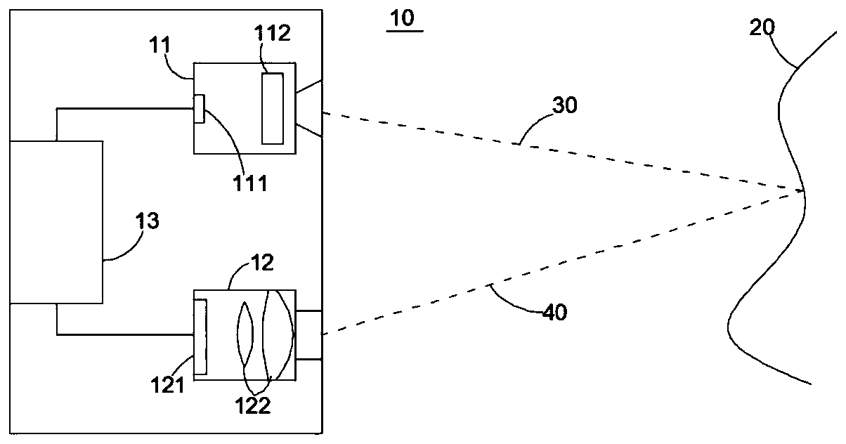
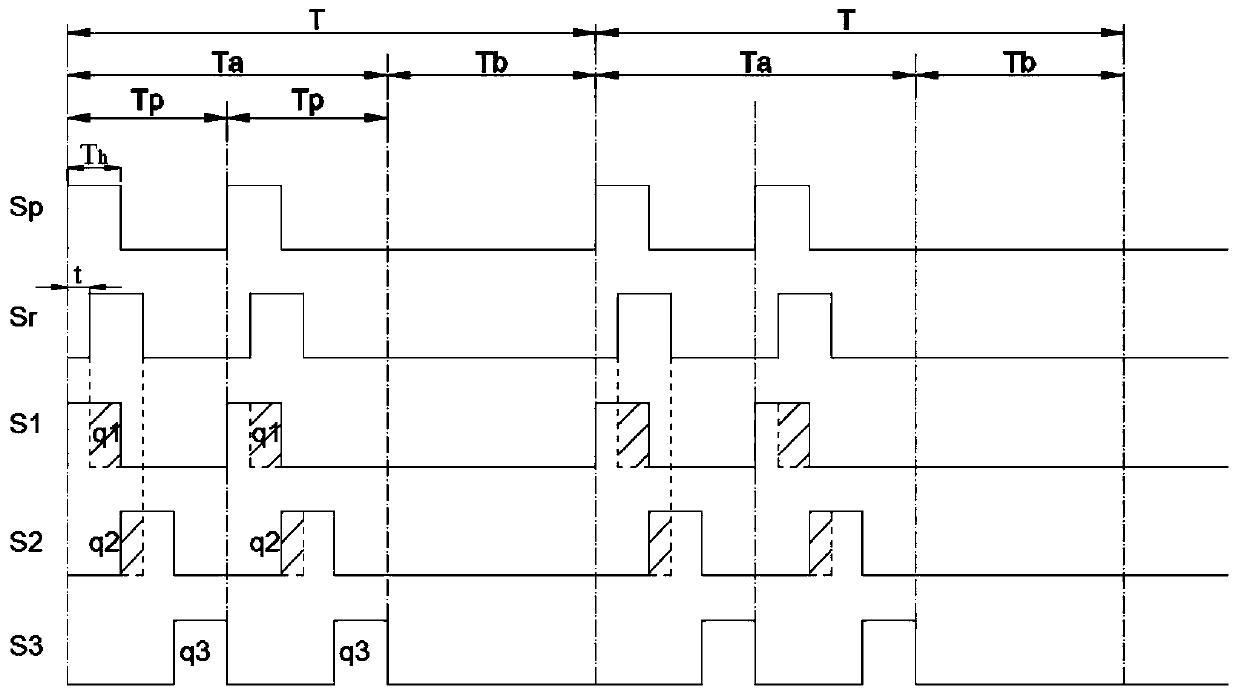
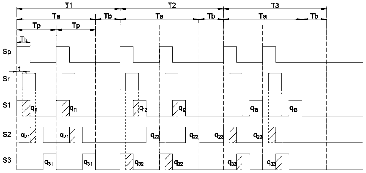
The invention provides a time depth camera and a multi-frequency modulation and demodulation distance measurement method for reducing noise. The time depth camera comprises: an emission module including a light source used for emitting a pulse light beam to an object to be measured; an acquisition module including an image sensor formed by at least one pixel, each pixel comprising at least three taps, and the taps being used for acquiring charge signals generated by the reflected pulse beams reflected by the object to be measured and/or charge signals of background light; and a processing circuit used for controlling the at least three taps to alternately acquire the charge signals among the at least three frame periods of a macrocycle, adopting different modulation and demodulation frequencies in every two adjacent macrocycles, and receiving data of the charge signals received in the two adjacent macrocycles to calculate the flight time of the pulse light beam and/or the distance of the object to be measured. The extension of the measurement distance is no longer limited by the pulse width, the fixed noise caused by mismatch between taps or between readout circuits due to processmanufacturing errors and the like is reduced or eliminated.

Description

technical field [0001] The invention relates to the technical field of optical measurement, in particular to a time-depth camera and a noise-reducing distance measurement method for multi-frequency modulation and demodulation. Background technique [0002] The full name of ToF is Time-of-Flight, that is, time of flight. The ToF ranging method is a technology that achieves precise ranging by measuring the round-trip flight time of light pulses between the transmitting / receiving device and the target object. In ToF technology, the technology of directly measuring the time of flight of light is called dToF (direct-TOF); the emitted optical signal is periodically modulated, and the phase delay of the reflected optical signal relative to the emitted optical signal is measured, and then by The measurement technology for calculating the time of flight by phase delay is called iToF (Indirect-TOF) technology. According to different modulation and demodulation methods, it can be divi...

Claims


Application Information

Patent Timeline
IPC IPC(8): G01S17/10G01S7/484G01S7/486
CPCG01S7/484G01S7/486G01S7/4865G01S17/26G01S17/894G01S17/86
Inventor 王飞朱亮胡小龙
Owner SHENZHEN ORBBEC CO LTD
Why Eureka
Try Eureka