Motion control device, motion control method, mask stage system and photoetching machine

A motion control device and motion module technology, applied in the field of lithography, can solve problems affecting the accuracy of a mask stage system and a lithography machine, and achieve the effects of reducing interference and improving motion accuracy

Active Publication Date: 2019-10-11
SHANGHAI MICRO ELECTRONICS EQUIP (GRP) CO LTD
View PDF4 Cites 0 Cited by
  • Summary
  • Abstract
  • Description
  • Claims
  • Application Information

AI Technical Summary

Problems solved by technology

[0005] The object of the present invention is to provide a motion control device, a motion control method, a mask table system, and a lithography machine to improve the problem that vibration affects the accuracy of the mask table system and lithography machine

Method used


Image

  • Motion control device, motion control method, mask stage system and photoetching machine
  • Motion control device, motion control method, mask stage system and photoetching machine
  • Motion control device, motion control method, mask stage system and photoetching machine

Examples


Embodiment 1

[0080] This embodiment provides a mask table system, which is applied to a motion control device and a photolithography machine in the mask table system.

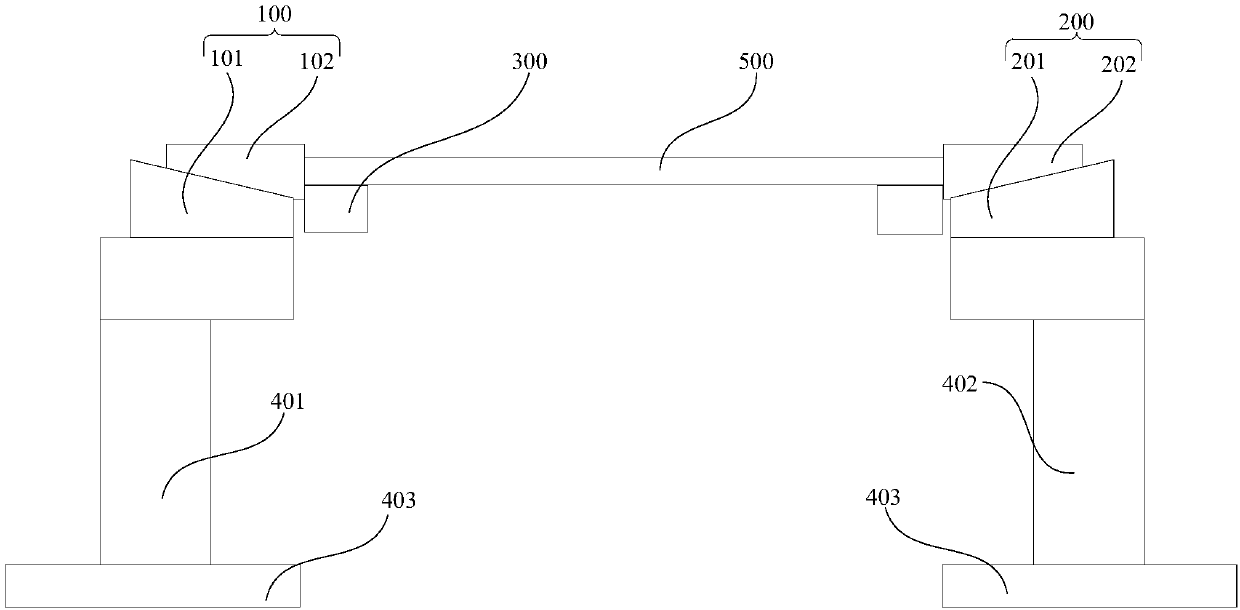
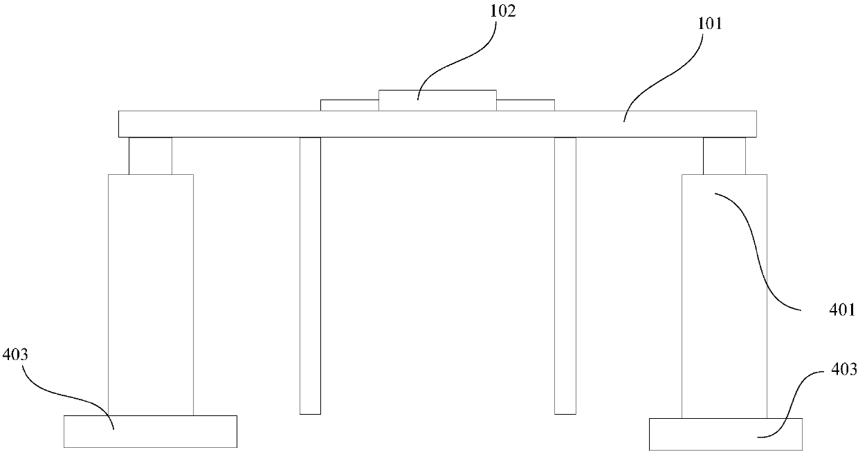
[0081] refer to Figure 4 and Figure 5 , Figure 4 is the front view of the mask stage system in Embodiment 1 of the present invention, Figure 5 It is a left view of the mask table system in Embodiment 1 of the present invention, the mask table system includes a first coarse motion module 810, a second coarse motion module 820, a mask table installation frame, a mask table 840, a motion control device, a position detection device, a first acceleration sensor and a second acceleration sensor.

[0082] The mask stage installation frame includes a first installation frame 831 and a second installation frame 832 . The first installation frame 831 and the second installation frame 832 are respectively set on the foundation 834 .

[0083] The first coarse motion module 810 and the second coarse motion module 820 are respec...

Embodiment 2

[0110] This embodiment provides a mask stage system. refer to Figure 7 , Figure 7 It is a front view of the mask table system in Embodiment 2 of the present invention. The difference between this embodiment and Embodiment 1 is that in this embodiment, the mask table system may further include a shock absorber 890 . In this embodiment, the coarse movement module is not directly arranged on the mask stage installation frame, but the shock absorber 890 is arranged on the mask stage installation frame, and the coarse movement module is arranged on The shock absorber 890 is on. The vibration transmitted from the foundation 834 passes through the mounting frame of the mask table, passes through the shock absorber 890 , and then transmits to the first coarse motion module 810 and the second coarse motion module 820 . Vibration transmitted to the mask table 840 by the lithography machine can be effectively reduced by providing a shock absorber 890 between the mask table mounting ...

Embodiment 3

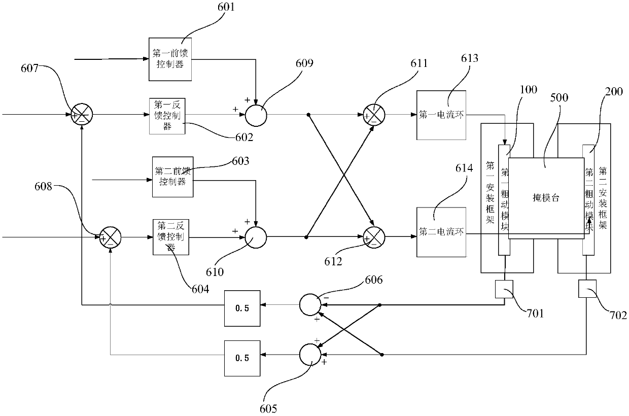
[0120] This embodiment provides a motion control method of the motion control device in the mask table system in the above embodiments. Before the motion control device works, it sends the motion track signal, the motion track acceleration signal of the first coarse motion module 810 and the motion track acceleration signal of the second coarse motion module 820 to the motion control device, and sends the first position information and the second The second position information is sent to the motion control device, and the acceleration information of the first installation frame 831 and the second installation frame 832 is sent to the motion control device.

[0121] The motion control method includes the steps of:

[0122] Step S10, the first position feedback unit converts the first position information and motion track signal into first drive information; the second position feedback unit converts the second position information and motion track signal into second drive info...


PUM


Abstract

The invention provides a motion control device, a motion control method, a mask stage system and a photoetching machine, which are used for controlling a first motion module and a second motion moduleto synchronously move and enabling the positions and motion track signals of the first motion module and the second motion module to meet preset requirements. The first motion module and the second motion module are respectively arranged on a first mounting frame and a second mounting frame. The motion control device comprises a first position feedback unit, a first track acceleration feedforwardunit, a first frame acceleration feedforward unit, a first addition operation module, a second position feedback unit, a second track acceleration feedforward unit, a second frame acceleration feedforward unit and a second addition operation module. The motion precision of the first motion module and the second motion module can be improved, and the mutual interference of the first motion moduleand the second motion module caused by asynchronous motion can be reduced, thereby improving the control precision of the motion control device.

Description

technical field [0001] The invention relates to the technical field of photolithography, in particular to a motion control device, a motion control method, a mask table system and a photolithography machine. Background technique [0002] The production equipment of large-scale semiconductor integrated circuits requires the vibration interference of many important components to be as small as possible, so that the important components are in a quiet environment. For example, the lithography machine requires the vibration interference of the workpiece table system and the mask table system to be as small as possible. The mask table of a lithography machine generally includes a micro-motion table and a coarse motion table. The micro-motion table completes the fine-tuning of the mask plate, and the coarse motion table completes the large-stroke scanning exposure movement of the mask plate. [0003] With the rapid development of the flat panel display industry, the size of the su...

Claims


Application Information

Patent Timeline
Patent Type & Authority Applications(China)
IPC IPC(8): G03F7/20G05D3/12
CPCG03F7/70758G03F7/70775G05D3/12G03F7/20
Inventor 卢彧文陈超廖飞红
Owner SHANGHAI MICRO ELECTRONICS EQUIP (GRP) CO LTD
Why Eureka
Try Eureka