Check patentability & draft patents in minutes with Patsnap Eureka AI!

Electronic control dismountable vehicle wheel deploying and retracting device and control method

A technology for retractable devices and wheels, applied to motor vehicles, amphibious vehicles, transportation and packaging, etc., can solve the problem that the suspension lift height cannot be kept constant and the wheel positioning parameters are within a reasonable range, and the control system controls operations and commands Response is not timely enough, increase the time required to complete the wheel retraction action, etc., to achieve the effect of reducing the complexity of the device, reducing the load of the actuator, and reducing the power of the actuator

Active Publication Date: 2019-10-15
WUHAN UNIV OF TECH
View PDF8 Cites 0 Cited by
  • Summary
  • Abstract
  • Description
  • Claims
  • Application Information

AI Technical Summary

Problems solved by technology

[0008] In terms of control, most of the existing amphibious vehicle wheel retractable devices adopt hydraulic control or mechanical structure control. Due to the hysteresis of the hydraulic system and the assembly gap of the mechanical structure, the response of the control system to control operations and commands is not timely enough, which increases the overall The time required to complete the wheel retraction action; the control accuracy is low, and the lifting height of the suspension cannot be guaranteed to be constant and the wheel positioning parameters are within a reasonable range

Method used


Image

  • Electronic control dismountable vehicle wheel deploying and retracting device and control method
  • Electronic control dismountable vehicle wheel deploying and retracting device and control method
  • Electronic control dismountable vehicle wheel deploying and retracting device and control method

Examples


Embodiment Construction

[0054] The present invention will be further described below in conjunction with specific examples and drawings.

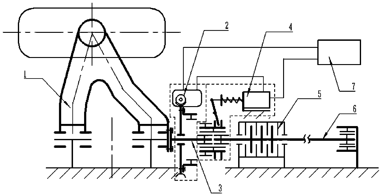
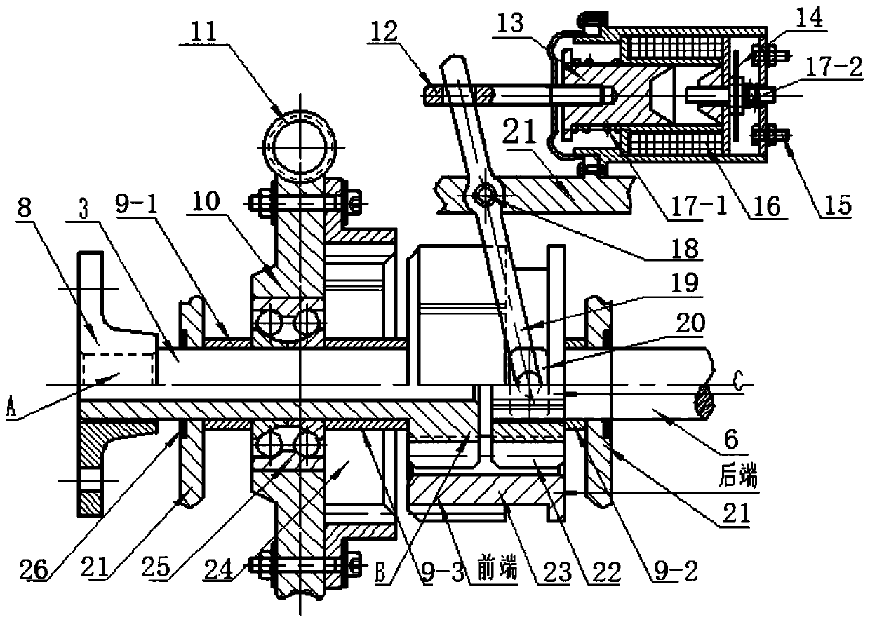
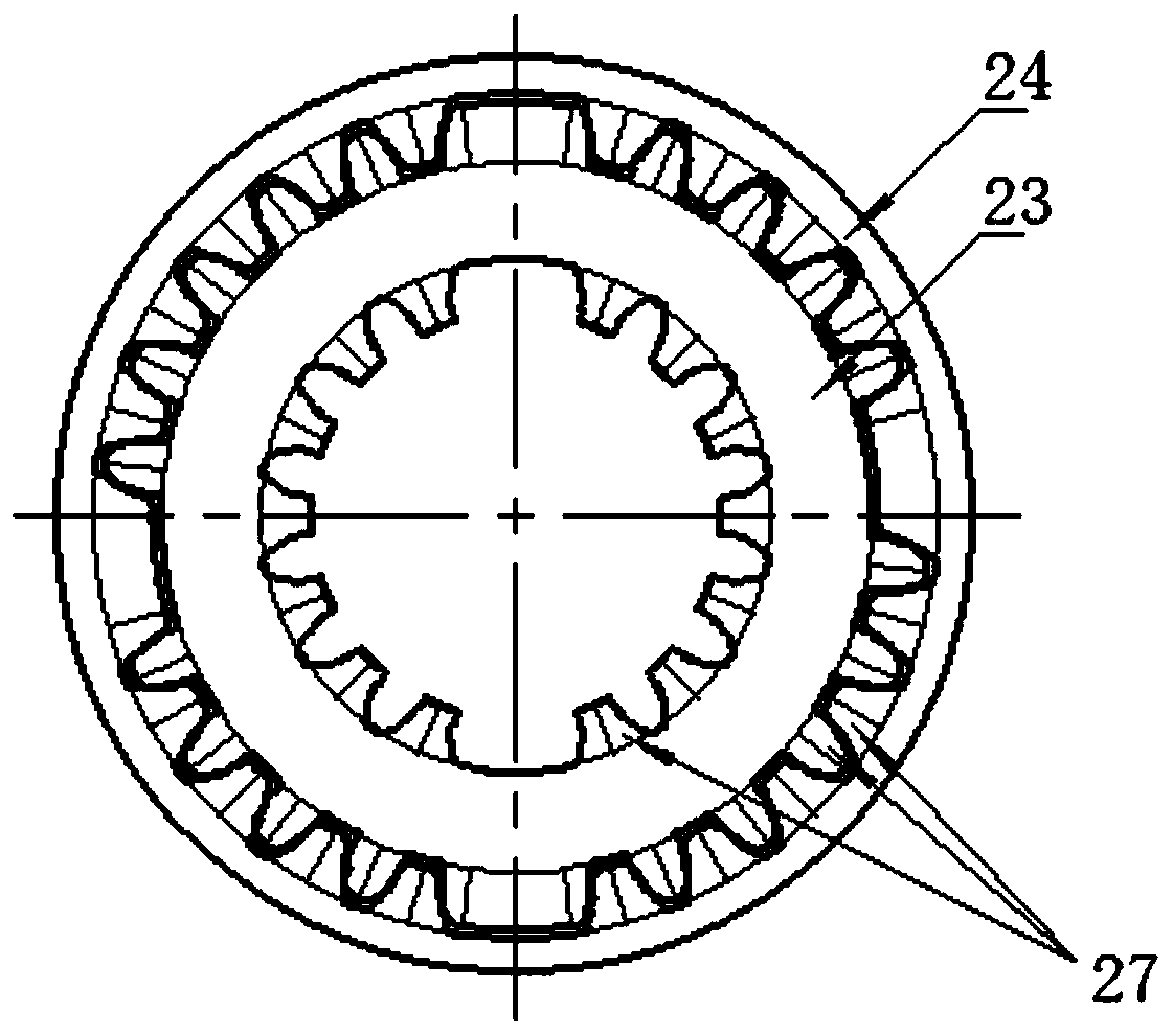
[0055] The invention provides an electronically controlled unloadable wheel retracting device based on a double wishbone suspension structure, such as Figure 1 to Figure 7 As shown, it includes a lower cross arm 1, a short drive shaft 3, a torsion bar spring 6, a wheel retracting actuator 2, an electromagnetic unloading mechanism 4, and a sliding spline sleeve 23. The lower cross arm 1 is fixedly connected to the short drive shaft 3; the short drive shaft 3 and the torsion bar spring 6 are arranged coaxially, and they are connected by a sliding spline sleeve 23; the wheel retracting actuator 2 is arranged on the short drive shaft 3, when the sliding spline sleeve 23 axially slides and is disconnected from the torsion bar spring 6, the short drive shaft 3 is retracted and retracted; the electromagnetic unloading mechanism 4 is connected with the sliding spline sleeve...


PUM


Abstract

The invention provides an electronic control dismountable vehicle wheel deploying and retracting device. The device comprises a lower cross arm, a transmission short shaft, a torsion rod spring, a vehicle wheel deploying and retracting actuator, an electromagnetic unloading mechanism and a sliding spline housing, wherein the lower cross arm is fixedly connected with the transmission short shaft; the transmission short shaft and the torsion rod spring are arranged coaxially, and can be connected through the sliding spline housing; the vehicle wheel deploying and retracting actuator is arrangedon the transmission short shaft and is used for driving the transmission short shaft, a suspension and vehicle wheels to rise when the sliding spline housing slides axially to be disconnected with thetorsion rod spring but connected with the vehicle wheel deploying and retracting actuator; the electromagnetic unloading mechanism is connected with the sliding spline housing, and is used for completing axial sliding of the sliding spline housing. By using the combination of the electromagnetic unloading mechanism and the vehicle wheel deploying and retracting actuator, rapid response can be realized, and the loads, applied to the vehicle wheel deploying and retracting device, of elastic and damping elements of the suspension in the vehicle wheel deploying and retracting process can be unloaded completely.

Description

Technical field [0001] The invention belongs to the field of amphibious condition switching equipment for wheeled amphibious vehicles, and particularly relates to an electronically controlled unloadable wheel retracting device and a control method. Background technique [0002] The amphibious vehicle is a special vehicle that has the characteristics of both a vehicle and a boat, which can travel on land and float on the water. Because of its excellent water and land traffic performance, it can quickly switch between land and water conditions without being restricted by roads, bridges, rivers, lakes, and seas. Therefore, it is used in military strategic maneuvers, water and land operations, disaster relief, tourism and entertainment, Professional fields such as transportation have outstanding advantages and special historical significance. [0003] The wheeled amphibious vehicle has wheels for on-land travel. The wheels can be used to paddle directly on the water or driven by a spe...

Claims


Application Information

Patent Timeline
IPC IPC(8): B60F3/00
CPCB60F3/00B60F3/003
Inventor 付翔杨鹏吴森
Owner WUHAN UNIV OF TECH
Features
  • R&D
  • Intellectual Property
  • Life Sciences
  • Materials
  • Tech Scout
  • Unparalleled Data Quality
  • Higher Quality Content
  • 60% Fewer Hallucinations
Learn More