Instrument desk framework convenient to assemble and installation method thereof
A technology of instrument panel and frame, which is applied in the field of instrument panel frame and installation that is easy to assemble. It can solve the problems of complex overall structure of instrument panel support, heavy instrument panel weight, and cumbersome installation process, so as to ensure the connection strength and seismic performance of the overall structure. , simple structure, and the effect of strengthening the overall structural strength
- Summary
- Abstract
- Description
- Claims
- Application Information
AI Technical Summary
Problems solved by technology
Method used
Image
Examples
Embodiment 1
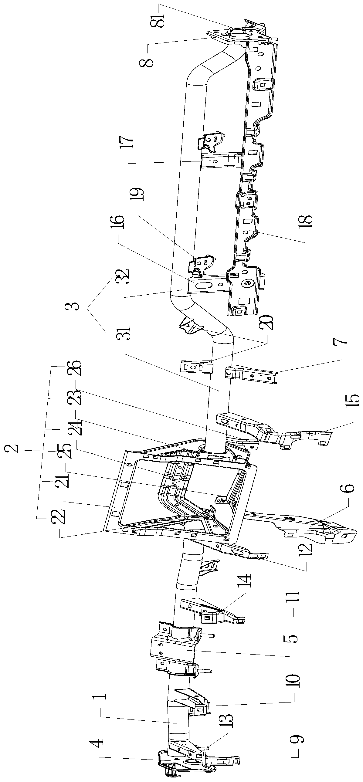
[0038] Such as Figure 1 to Figure 4 As shown, an instrument panel skeleton that is easy to assemble includes a first tube beam 1, a middle instrument mounting assembly 2 and a second tube beam 3 from left to right. Compared with the instrument panel skeleton in the prior art, the entire instrument panel skeleton is simplified and integrated It is organized into three parts to facilitate the later installation and maintenance work and improve its installation efficiency.
[0039] The left end of the first tube beam 1 is welded and fixed with a left side mounting bracket 4 connected to the cab body, thereby providing the left side support strength of the frame. The middle part of the first tube beam 1 is welded and fixed with the left side guard plate connection structure for fixing the instrument panel body and the combined instrument bracket 5 for installing the instrument, and the right end of the first tube beam 1 is welded and fixed to the middle instrument installation assem...
Embodiment 2
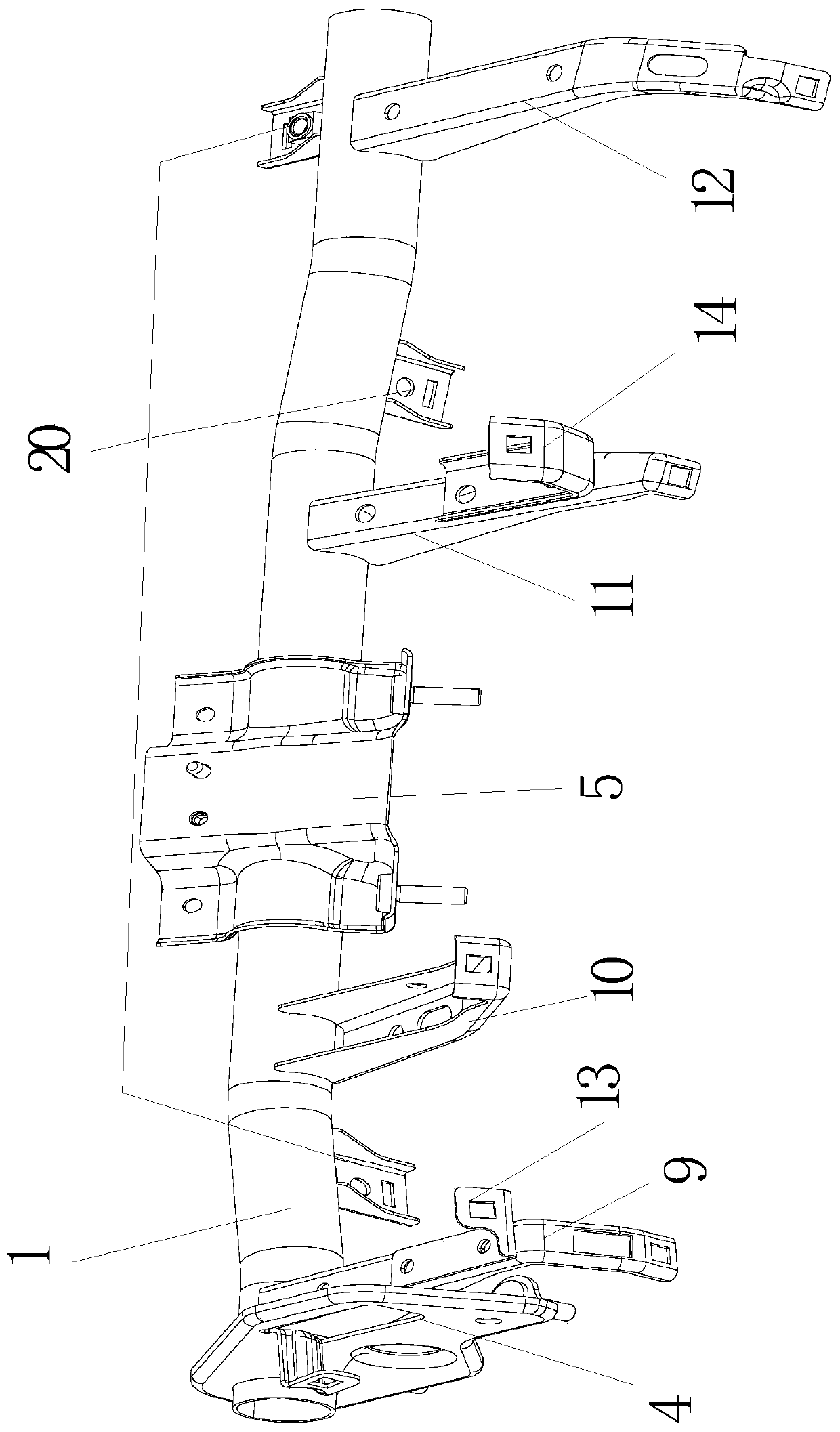
[0047] Such as image 3 As shown, the optimized solution obtained on the basis of Example 1, the left side guard plate connection structure includes a left lower guard plate bracket 9, a right lower guard plate bracket 10, a middle and lower guard plate bracket 11 and The middle and lower guard plate bracket two 12 is used to fix and support the instrument panel body to ensure the stability of the instrument panel, even when the car is running at high speed or complicated road sections, it cannot generate vibration and maintain the corresponding reliable connection. One end of the left lower guard plate bracket 9, the right lower guard plate bracket 10, the middle and lower guard plate bracket 11, and the middle and lower guard plate bracket 2 12 are all welded and fixed to the first pipe beam 1, and they are all provided with stress relief holes. The other ends of the guard plate bracket 9, the right lower guard plate bracket 10, the middle and lower guard plate bracket 11, and...
Embodiment 3
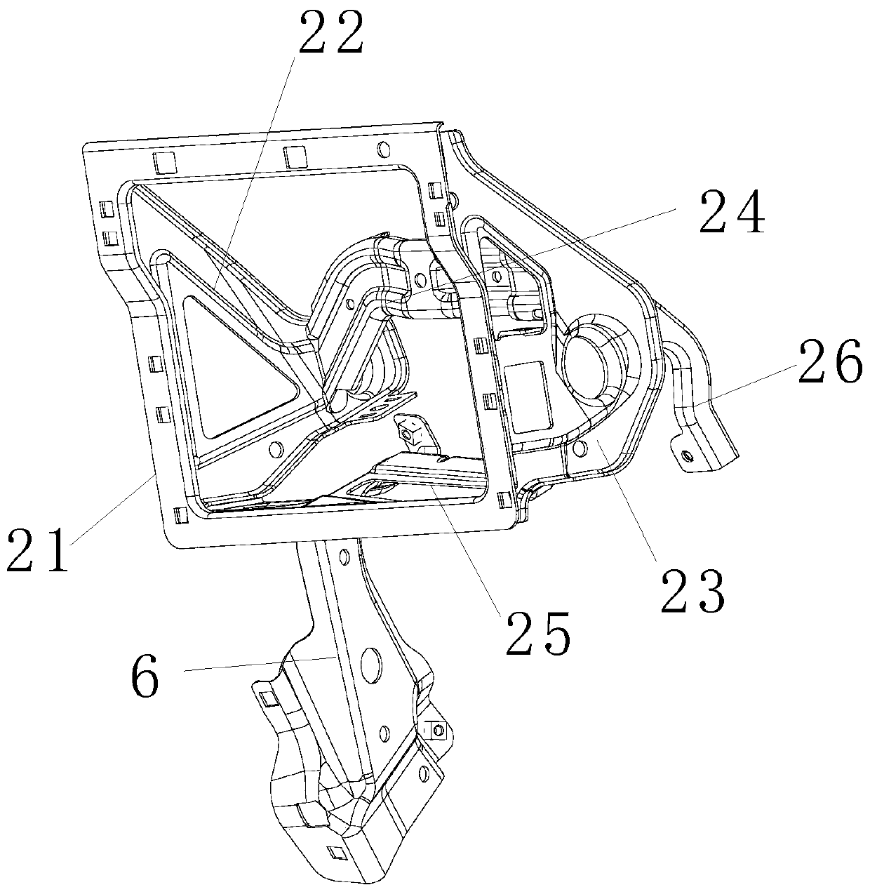
[0049] Such as figure 2 As shown, an optimized solution obtained on the basis of embodiment 1, the middle instrument mounting assembly 2 includes a mounting bracket 21, a mounting bracket 2 22, a mounting bracket 3 23, a rear support bracket 24 and a bottom connecting bracket 25, and a mounting bracket 1 21 is a lip-shaped structure, and the mounting bracket 21 is provided with a number of circumferentially arranged and rectangular display mounting holes to facilitate the installation of instruments of different sizes. Mounting bracket two 22, mounting bracket three 23, rear support bracket 24, and bottom connecting bracket 25 are provided with meter connection holes for connecting and strengthening the meter to prevent vibration from affecting the use effect. The second mounting bracket 22 is welded and fixed on the left side of the rear of the first mounting bracket 21, and the surface is provided with holes for connecting with the first pipe beam 1, weight-reducing holes and...
PUM
 Abstract
Description
Claims
Application Information
 - R&D
- Intellectual Property
- Life Sciences
- Materials
- Tech Scout
- Unparalleled Data Quality
- Higher Quality Content
- 60% Fewer Hallucinations
Browse by: Latest US Patents, China's latest patents, Technical Efficacy Thesaurus, Application Domain, Technology Topic, Popular Technical Reports.
© 2025 PatSnap. All rights reserved.Legal|Privacy policy|Modern Slavery Act Transparency Statement|Sitemap|About US| Contact US: help@patsnap.com


