Supercharge Your Innovation With Domain-Expert AI Agents!

Centrifugal elevator speed limiter

An elevator speed limiter and centrifugal technology, which is applied in the field of elevator speed limiters and centrifugal elevator speed limiters, can solve the problems of large space occupation, increased production costs, damage to speed limiters or braking devices, etc., and achieve improved The degree of automation, the effect of saving production cost and reducing the installation space

Pending Publication Date: 2019-10-15
SHIJIAZHUANG TONGAN MACHINERY CO LTD
View PDF0 Cites 1 Cited by
  • Summary
  • Abstract
  • Description
  • Claims
  • Application Information

AI Technical Summary

Problems solved by technology

[0003] In the prior art, there is an elevator speed limiter. When the speed of the elevator car exceeds the preset speed, the centrifugal throwing block swings under the action of centrifugal force, triggering the trigger lever on the electrical switch, so that the elevator system is powered off. When the car is running at an overspeed limit, the speed limiter acts mechanically, and the rope clamp block in the clamping mechanism clamps the wire rope to generate a stable pulling force, which triggers the action of the safety brake device. After the mechanical operation of the speed limiter triggers the action of the safety gear, the wire rope needs to Slipping, the clamping block in the clamping mechanism that is in contact with the wire rope is easy to wear, so it needs to be inspected, adjusted or replaced regularly. At the same time, the clamping force of the clamping mechanism should not be too large, otherwise it will cause damage to the speed limiter or braking device
[0004] The above-mentioned speed limiter needs to use special testing equipment to adjust the lifting force of the speed limiter before leaving the factory to meet the actual use requirements. The operation is complicated and time-consuming, and the structure of this kind of speed limiter is complicated, which increases the production cost. Due to the setting of the clamping mechanism, it takes up a lot of space when it is installed; and there is only one limiter for limiting the rotation angle of the ratchet in this speed governor. When meshing to realize emergency stop, the torque generated by the meshing of the ratchet and the pawl is transmitted to the machine base through the limiter. After a long time of use, the part of the machine base with the limiter is deformed, resulting in unstable performance of the speed limiter. , The safety factor is reduced, and the service life of the elevator speed limiter is shortened

Method used


Image

  • Centrifugal elevator speed limiter
  • Centrifugal elevator speed limiter
  • Centrifugal elevator speed limiter

Examples


Embodiment

[0027] Example Centrifugal Elevator Speed ​​Governor

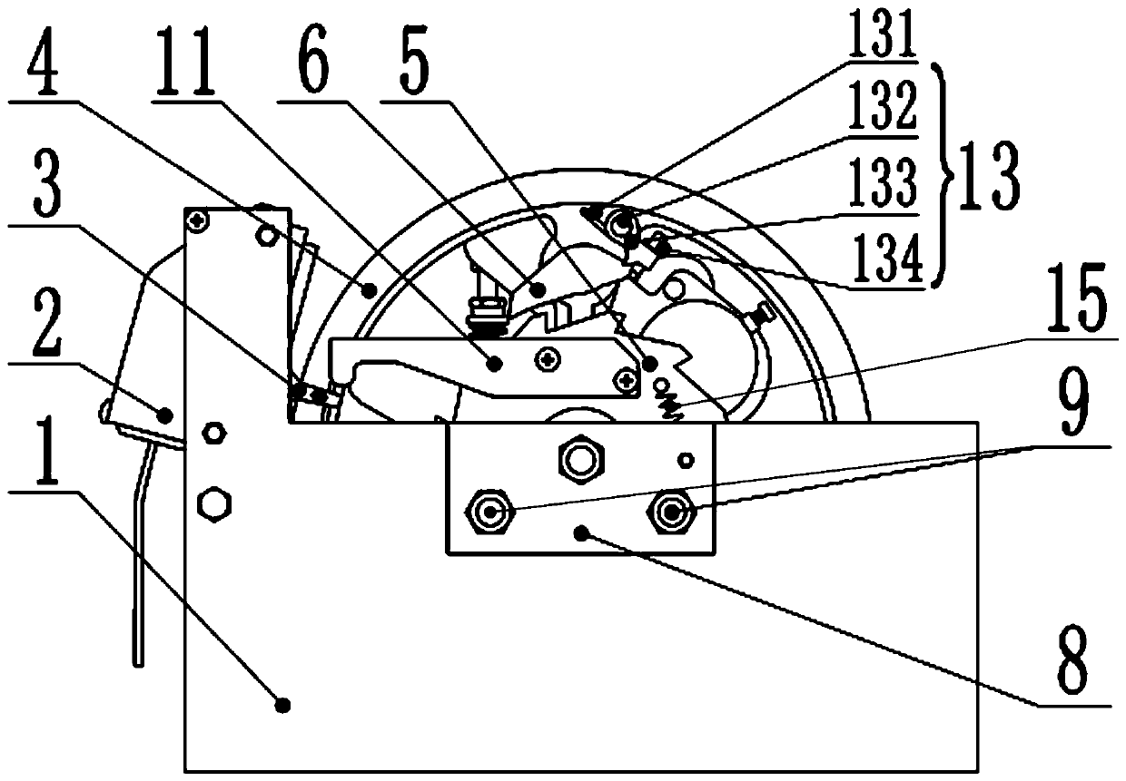
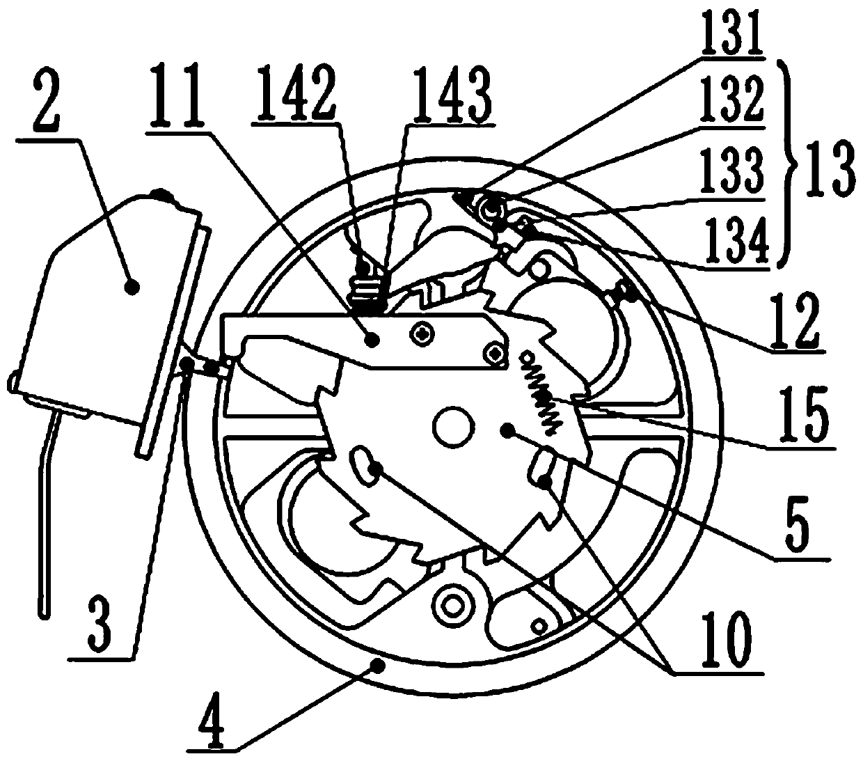
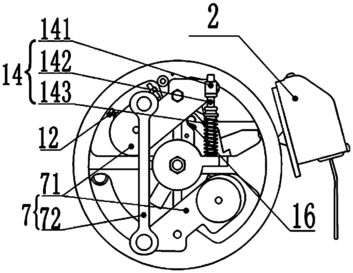
[0028] This example figure 1 , figure 2 , image 3 , Figure 4 As shown, a centrifugal elevator speed governor includes a machine base 1, an electrical switch 2 fixed on the machine base 1, a sheave 4 connected to the machine base 1 through the sheave shaft rotation, and a sheave 4 rotatably connected to the sheave shaft The ratchet 5, the electrical switch 2 is fixed with a trigger lever 3 for powering off the elevator system; the sheave 4 is provided with four spokes, and the sheave 4 is circumferentially arranged for winding the wire rope The groove is a V-shaped groove with a notch, and the wire rope connected to the elevator car goes around the V-shaped groove on the sheave 4. The frictional traction between the two hypotenuses of the V-shaped groove and the wire rope generates a stable Therefore, the clamping mechanism in the prior art can be omitted, the volume of the elevator speed governor can be reduced, and...


PUM


Abstract

The invention discloses a centrifugal elevator speed limiter. The centrifugal elevator speed limiter comprises a machine base, an electrical switch fixedly arranged on the machine base, a rope sheavewhich is rotationally connected to the machine base through a rope sheave shaft, and a ratchet wheel which is rotationally connected to the rope sheave shaft. The rope sheave is rotationally connectedwith a pawl and a centrifugal throwing block assembly through a pawl shaft, the pawl is matched with the ratchet wheel, the centrifugal throwing block assembly and the pawl synchronously swing, a limiting device used for guaranteeing that the pawl and the ratchet wheel are staggered when the speed limiter normally works is arranged between the pawl and the centrifugal throwing block assembly, anda groove used for winding a steel wire rope and formed in the circumferential direction of the rope sheave is a V-shaped groove with a notch. At least one arc-shaped clamping hole which extends in the circumferential direction of the rope sheave is formed in the ratchet wheel, and the machine base is fixedly provided with limiting stop shafts which extend into the clamping holes respectively andused for limiting the rotation angle of the ratchet wheel. A switch striking plate is fixedly arranged on the ratchet wheel. The speed limiter is simple and convenient to operate, stable and reliablein performance, small in required installation space, long in service life, high in safety coefficient and suitable for all elevator speed limiters, with the rated speed lower than or equal to 2.5 m / s, of machine rooms.

Description

technical field [0001] The invention belongs to the field of elevators, and relates to an elevator speed governor, in particular to a centrifugal elevator speed governor. Background technique [0002] The elevator speed limiter is one of the safety control components in the elevator safety protection system. When the elevator descends at an overspeed due to some reason of abnormal operation, and the descending speed reaches the preset limit value, the elevator speed limiter will act, or The elevator speed limiter is linked with the safety gear to stop the elevator car. [0003] In the prior art, there is an elevator speed limiter. When the speed of the elevator car exceeds the preset speed, the centrifugal throwing block swings under the action of centrifugal force, triggering the trigger lever on the electrical switch, so that the elevator system is powered off. When the car is running at extreme overspeed, the speed limiter acts mechanically, and the rope clamp block in t...

Claims


Application Information

Patent Timeline
Patent Type & Authority Applications(China)
IPC IPC(8): B66B5/04B66B5/26
CPCB66B5/044B66B5/26
Inventor 李宏图任龙福刘鸿坤王彦存
Owner SHIJIAZHUANG TONGAN MACHINERY CO LTD
Features
  • R&D
  • Intellectual Property
  • Life Sciences
  • Materials
  • Tech Scout
  • Unparalleled Data Quality
  • Higher Quality Content
  • 60% Fewer Hallucinations
Learn More